Author:David Ran
This article discusses steel building components, fabrication, and project planning. Project-specific technical requirements should be confirmed during engineering review.
Share This :
Steel Structure Drawings: A Practical Guide for Buyers
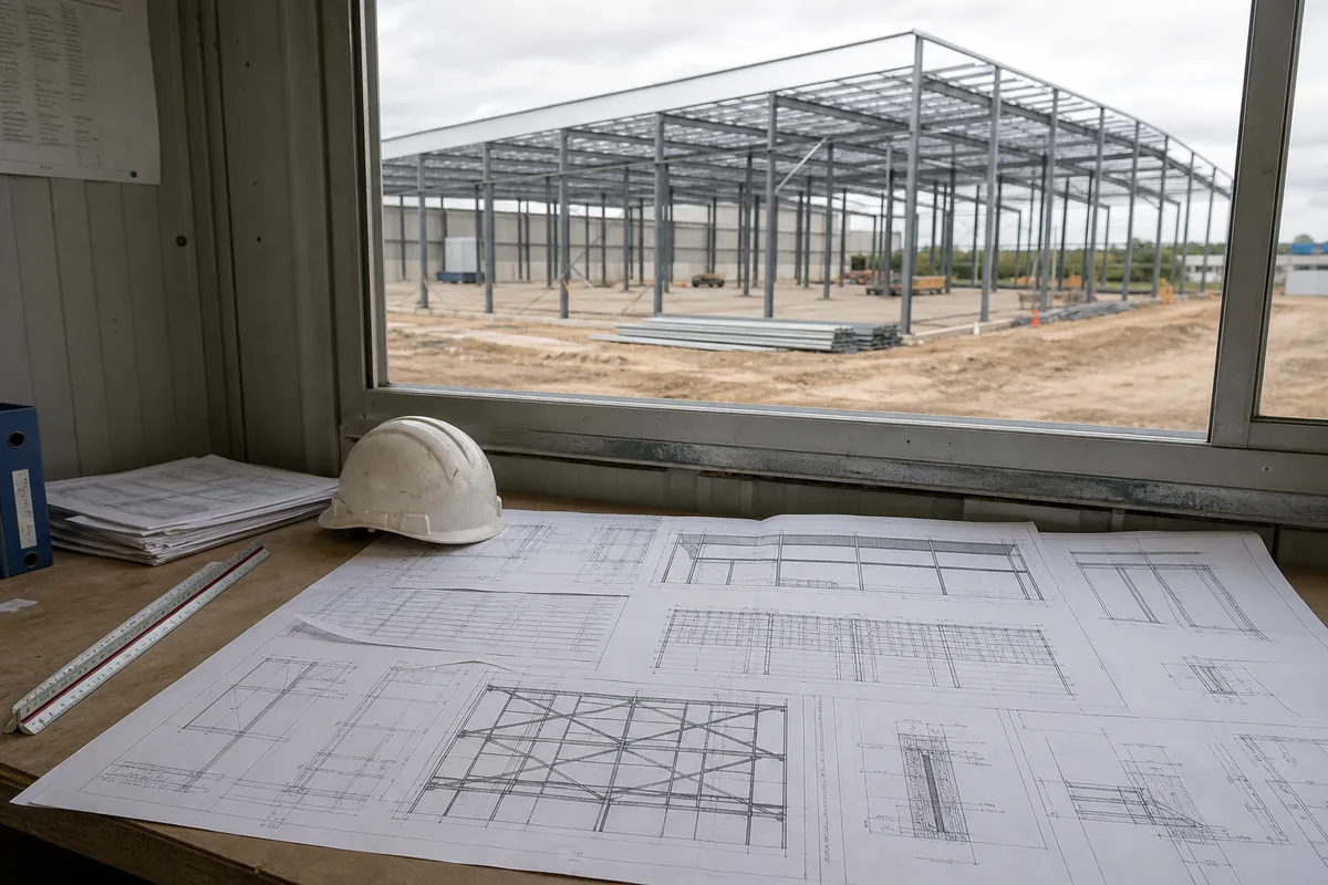
Steel structure drawings turn a buyer’s building requirements into information that designers, fabricators and erection teams can follow. They show the building geometry, structural members, connections, materials and installation positions that must work together in the finished project.
Buyers do not need to calculate beam strength or design welded connections. However, they should be able to confirm the information that affects the building’s operation: overall dimensions, clear height, column locations, doors, cranes, mezzanines, cladding, equipment openings and future expansion. A missed detail at the approval stage can become an expensive site change after fabrication begins.
This practical guide explains how to read the main types of steel building drawings, what buyers should check, and where professional engineering review remains essential.
What Are Steel Structure Drawings?
Steel structure drawings are the graphic documents used to communicate the design, fabrication and erection requirements of a steel-framed building. A complete drawing package usually contains several coordinated sheets rather than one drawing.
Depending on the project stage, the drawings may define:
- Building length, width, height and roof geometry
- Gridlines and column positions
- Primary and secondary steel members
- Base plates, anchor bolts and foundations
- Bolted and welded connections
- Roof and wall cladding layouts
- Doors, windows, ventilation and equipment openings
- Fabrication dimensions and erection locations
The drawing package should be read together with project specifications, design criteria and the latest approved revision. A single sheet rarely contains every requirement.
Main Types of Steel Building Drawings
1. General Arrangement Drawings
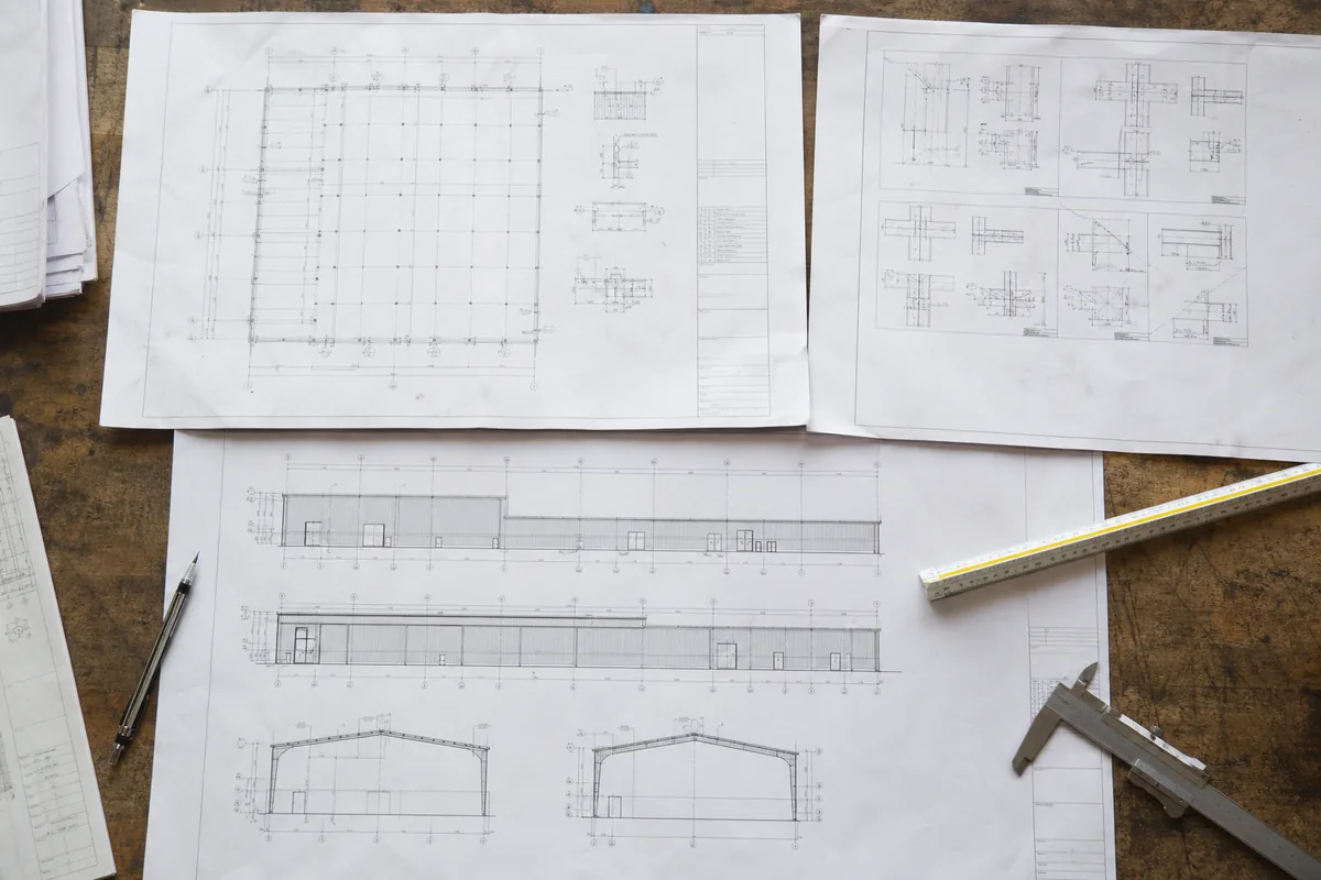
General arrangement drawings provide the overall view of the building. They normally include plans, elevations and sections. Buyers should begin here because these sheets show the main dimensions, structural grids, roof shape and major openings.
2. Foundation and Anchor-Bolt Drawings
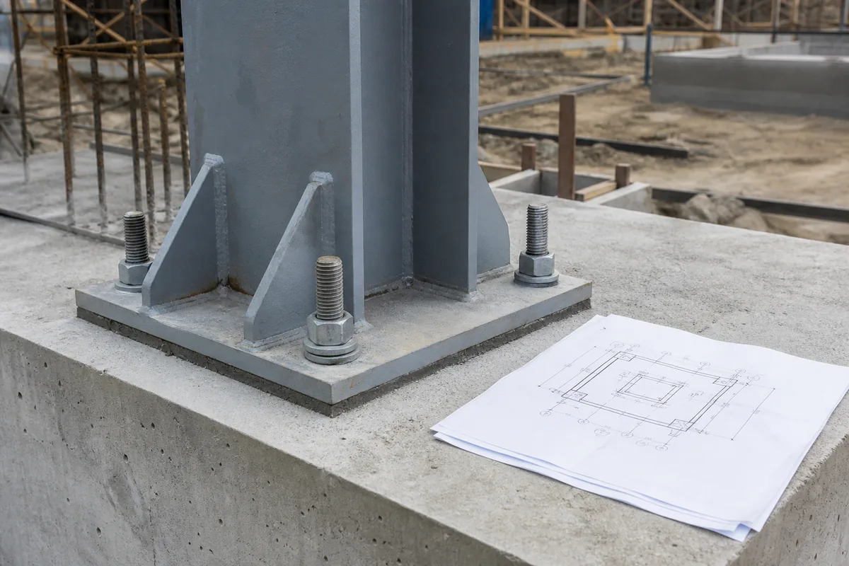
Foundation drawings show column reactions or foundation geometry, depending on the supplier’s scope. Anchor-bolt drawings define bolt groups, centerlines, projection and orientation. These documents must be coordinated with the local civil engineer before concrete is poured.
3. Structural Design Drawings
Structural design drawings describe the framing system and the size or type of columns, rafters, beams, bracing and other load-carrying elements. They communicate the design intent used to prepare more detailed fabrication documents.
4. Fabrication or Shop Drawings
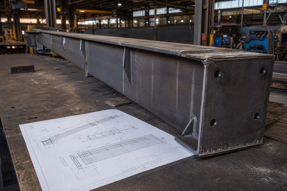
Steel fabrication drawings provide the information needed to manufacture individual components. They can include exact member lengths, plate dimensions, hole positions, welds, material grades, surface treatment and shipping-piece marks.
5. Erection Drawings
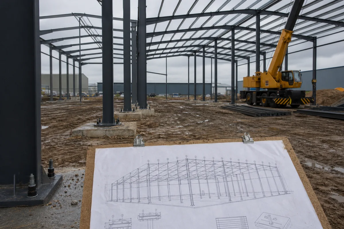
Steel erection drawings show where each fabricated shipping piece is installed. Member marks on the drawing should match the marks applied to delivered steel components, helping the site team identify columns, rafters, bracing and connection hardware.
6. Roof and Wall Cladding Drawings
Cladding drawings show panel direction, lengths, laps, trims, flashings, gutters, downpipes, skylights and openings. They are important even when the structural frame itself is correct, because enclosure details affect weather resistance and appearance.
How to Read Plans, Elevations and Sections
A plan is a view looking down on the building. It is used to check the footprint, gridlines, column spacing, bays, doors and internal layout. Elevations show the exterior faces and help buyers verify eave height, ridge height, wall openings and roof form. Sections cut through the building to reveal internal clearances and the relationship between floor, structure and roof.
Gridlines connect these views. A column at grid intersection B-4 on the plan should appear at the same location in the relevant elevation or section. When reviewing structural steel drawings, buyers should use grid references instead of relying only on the apparent position of an item on the page.
Seven Essentials Buyers Must Check
1. Title Block, Status and Revision
Before checking dimensions, identify the project name, drawing number, issue date, scale, revision and drawing status. A sheet marked for review may not be approved for fabrication. When a new revision is issued, obsolete copies should be removed from the active project files.
2. Overall Dimensions and Clear Space
Confirm the overall length, width, eave height and roof slope. Then check usable dimensions: clear internal height below rafters, clear width between columns, crane clearance, mezzanine headroom and space around production equipment. Overall height and usable height are not always the same.
3. Gridlines and Column Locations
Check bay spacing and every internal column. A column that conflicts with a loading route, machine, conveyor or storage aisle can disrupt operations even if it is structurally acceptable. For a future extension, confirm which end wall is designed to accommodate expansion.
4. Openings and Accessories
Verify the size, sill height and grid location of doors, windows, louvers, fans and service penetrations. Confirm gutters, downpipes, canopies, stairs, handrails and skylights. Large openings may require additional framing, so they should be finalized before production.
5. Member Marks and Connection References
Columns, rafters, beams and bracing are normally assigned marks such as C1, R2 or BR3, although each supplier may use a different system. These marks connect the general arrangement, shop drawing, packing list and erection drawing. Buyers should check that referenced details exist and that the same mark is used consistently.
6. Materials, Coatings and Cladding
Confirm the specified steel grades, bolt grades, paint system or galvanizing, roof and wall panel type, insulation thickness and panel colors. A drawing approval should reflect the commercial agreement. If corrosion exposure or fire protection is important, make sure the requirements are clearly documented.
7. Loads and Project-Specific Requirements
The design criteria should match the project location and use. Confirm wind, snow and seismic information, crane capacity and duty, mezzanine loading, suspended equipment, solar panels and any future loads. Buyers should provide operational information, while a qualified engineer determines the structural calculations under the applicable code.
Understanding Member Sizes, Bolts and Weld Symbols
Member schedules list the section or fabricated profile assigned to each mark. Dimensions may be in millimeters or another declared unit. Never assume the unit from appearance alone; check the general notes and title block.
Connection details can show plates, stiffeners, bolt quantities, hole diameters and weld symbols. Buyers are not expected to verify connection capacity. Their role is to confirm that functional requirements are present and to make sure the drawings have been reviewed by the responsible engineering and fabrication teams.
If a connection detail is unclear, request a written clarification rather than making assumptions at the jobsite. Unapproved field cutting, drilling or welding can change the designed load path and damage protective coatings.
From Approval Drawings to Fabrication and Erection
A typical steel building drawing workflow follows these stages:
- The buyer provides the project location, dimensions, use, loads and accessories.
- The supplier prepares proposal or approval drawings.
- The buyer, local consultants and equipment teams review the layout.
- Comments are incorporated and a new revision is issued.
- The final geometry and specifications are formally approved.
- Detailed shop drawings are released for fabrication.
- Erection drawings and component marks guide installation.
The exact responsibilities should be defined in the contract. Approval does not transfer structural-design responsibility to an unqualified buyer, but it does confirm that the supplier has correctly understood the buyer’s functional and commercial requirements.
Foundation and Anchor-Bolt Coordination
The interface between the steel structure and concrete foundations deserves special attention. Check grid dimensions, base-plate levels, anchor-bolt spacing, bolt projection and the orientation of asymmetrical bolt groups. The foundation engineer also needs reliable column reactions and local soil information.
Before concrete placement, the contractor should verify templates, diagonals, levels and bolt locations. Correcting an anchor-bolt error after the pedestal has cured is far more difficult than identifying a mismatch in the steel structure drawings.
What Buyers Should Approve—and What Engineers Must Verify
Buyers are best placed to approve operational and commercial information: dimensions, building use, openings, equipment, colors, accessories, clearances and the intended construction scope. The responsible engineer must verify loads, stability, member capacity, connection design, serviceability and compliance with local regulations.
For an exported steel building, local approval requirements should be discussed early. A supplier may prepare structural documents and calculation information, but a locally licensed professional may still be required to review or adapt the design for permits.
Common Drawing Review Mistakes
- Reviewing only the floor plan: elevations and sections may reveal height or clearance conflicts.
- Using an outdated revision: fabrication and civil work must use the current approved issue.
- Ignoring equipment layouts: machines, racks and conveyors should be coordinated with columns and bracing.
- Changing openings after fabrication: late changes can require new steelwork, panels and delivery arrangements.
- Assuming every item is included: confirm the supply scope for foundations, cladding, accessories and installation.
- Approving unclear information: record questions and obtain a revised drawing or written response.
Steel Structure Drawing Approval Checklist
- Project name, drawing number and latest revision are correct.
- Overall length, width, height, span and bay spacing are correct.
- Columns and bracing do not obstruct operations.
- Doors, windows and equipment openings match the intended layout.
- Crane, mezzanine, solar and suspended loads are declared.
- Roof, wall, insulation, colors and accessories match the quotation.
- Foundation and anchor-bolt information is coordinated.
- Local design criteria and approval responsibilities are confirmed.
- All review comments are closed before fabrication release.
Why Choose Bingfa Steel?
Bingfa Steel provides customized steel structure solutions for warehouses, workshops, factories, agricultural buildings and commercial projects. Our work can include design communication, detailed drawings, steel fabrication, roof and wall systems, export packing and installation guidance.
Clear drawings help connect the buyer’s requirements with factory production and site erection. To request a proposal, provide the project city, building dimensions, application, environmental loads, openings, crane or mezzanine requirements and preferred cladding system. You can also review our steel workshop buildings or contact our team with your project information.
External Technical Reference
The American Institute of Steel Construction distinguishes design documents, fabrication documents and erection documents in its industry guidance. Buyers and project teams can consult the AISC Code of Standard Practice terminology overview when defining drawing responsibilities.
FAQ
1. What drawings should a steel building supplier provide?
The required package depends on the contract, but it commonly includes general arrangement, anchor-bolt, structural, fabrication, erection and cladding drawings. The exact scope and approval responsibility should be agreed before design begins.
2. What is the difference between design drawings and shop drawings?
Design drawings communicate the structural design and overall project requirements. Shop drawings translate that information into the dimensions, materials, holes, plates and welds needed to manufacture individual steel components.
3. Can fabrication start before drawings are approved?
Fabrication should not be released until the required drawings and project information have reached the agreed approval status. Starting early increases the risk of rework when dimensions, openings or specifications change.
4. Who checks the structural calculations?
A qualified structural engineer should prepare or verify the calculations. Depending on the project location, review by a locally licensed engineer or approval authority may also be required.
5. What information should buyers provide before drawing work starts?
Provide the project location, building use, length, width, height, column restrictions, openings, loads, cranes, mezzanines, equipment, insulation, cladding and future expansion requirements. More complete input produces more accurate steel structure drawings and quotations.
Get Steel Structure Drawings for Your Project
Good drawings reduce uncertainty before steel is fabricated and shipped. Send Bingfa Steel your building dimensions, project location, intended use and special requirements. Our team can discuss a suitable steel structure solution, drawing scope and quotation for your project.
FAQ
① What is a steel structure building?
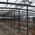
A steel structure building is a construction made primarily from high-strength steel components such as H-beams and columns. It is widely used for warehouses, workshops, poultry farms, and industrial facilities due to its durability and cost efficiency.
②How much does a steel building cost?
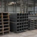
Steel building costs depend on dimensions, structural loads, material specifications, project location and the agreed scope of supply. A preliminary quotation can start with the main steel structure. Roof and wall panels, freight, foundations and installation should be considered separately when required. Customized solutions may vary based on specific requirements.
③How long does it take to build a steel structure?
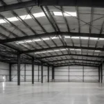
Manufacturing lead times depend on the building dimensions, structural complexity, material specifications and production schedule. An estimated production timeline can be provided after reviewing the project requirements. Installation duration depends on site conditions, building complexity and the agreed scope of work.
④Do you provide installation support?
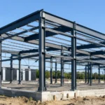
Installation documentation and technical support depend on the agreed scope of each project. If you require installation assistance, please let us know during the inquiry so we can review the available options, responsibilities and local requirements.
⑤Can steel buildings withstand extreme weather?

Steel buildings can be engineered for project-specific wind, snow and seismic loads, subject to applicable design codes, structural calculations and local site conditions. The required design loads and standards must be confirmed before structural engineering begins.