Steel structure building components include the main steel frame, columns, beams, rafters, purlins, girts, bracing systems, roof and wall panels, anchor bolts, and foundation connections. Understanding these parts helps building owners, engineers, and contractors choose the right design, control costs, and improve long-term performance.
Author:David Ran
Position:Senior Steel Structure Engineer at BF Steel Structure.
Introduction:With over 16 years of experience in steel structure design, fabrication, and project management, David has participated in more than 500 industrial steel building projects worldwide, including warehouses, workshops, agricultural buildings, and commercial steel structures.
Share This :
No individual structural steel building you will see (i.e., the 50′ x 50′ warehouse or the large multi-story office building) is a group of interdependent components that must all do their own job. Remove a piece or specify one incorrectly and the overall performance will be compromised. To those who own the building and are responsible for approving designs, engineers or architects who are specifying materials, and contractors who are responsible for the erection of the steel structure you should have an understanding of the primary components of steel structure building.
The difference between Selling a building that lasts 50 years vs Selling a building that develops problems in the first 10 years can be primarily attributed to top decision makers when they are Selecting designing and connecting the individual structural elements in their buildings.
This guide will provide you with a list and description of all major Steel structure elements to assist you in making informed decisions throughout the process (from the grade of steel used in the building frame to the anchor bolts in the building’s foundation).
Core Structural Steel Framing Types and Materials
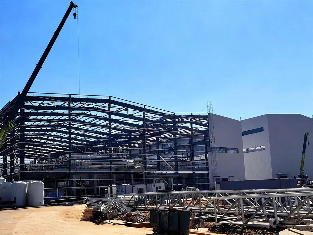
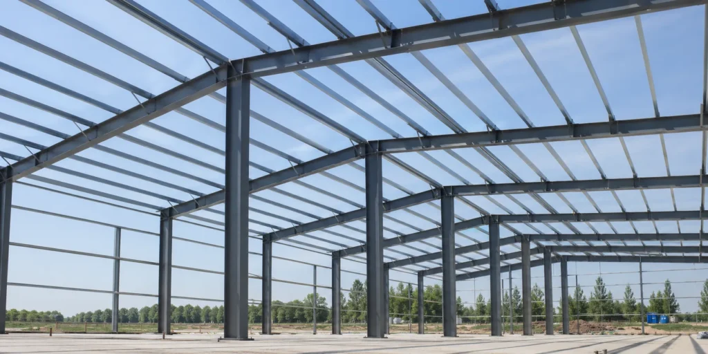
The frame is the skeleton. Everything else – walls, roof, insulation, accessories – hangs on it or braces against it. Choosing the right steel grade and frame configuration sets the trajectory for cost, clear span capability, and long-term performance.
Carbon and High-Strength Low-Alloy Steel Grades
Most steel buildings in 2026 use ASTM A992 for wide-flange shapes (columns and beams) and ASTM A572 Grade 50 for plates and built-up sections. Both offer a minimum yield strength of 50 ksi, which hits the sweet spot between strength and weldability. For lighter secondary members like purlins and girts, A653 galvanized coil steel (typically Grade 50 or 80) is standard because it resists corrosion without requiring field painting.
High-strength low-alloy (HSLA) steels contain small amounts of niobium, vanadium, or titanium. These micro-alloying elements refine the grain structure, letting engineers specify thinner sections that still carry the required loads. The result is less steel tonnage per building, which translates directly to lower material and shipping costs.
If your building faces corrosive environments – coastal salt air, chemical processing fumes, fertilizer storage – consider weathering steel (A588) or upgraded coating systems. The steel grade decision should happen early because it affects connection design, welding procedures, and fabrication lead times.
Clear-Span vs. Multi-Span Rigid Frame Designs
Clear-span rigid frames use no interior columns. They’re the default choice for warehouses, aircraft hangars, and riding arenas where unobstructed floor space matters. Practical clear spans reach about 200 feet, though most projects fall between 60 and 120 feet. The tradeoff: as span increases, rafter depth grows, which raises material weight and eave height.
Multi-span frames introduce interior columns at regular intervals (typically 40 to 80 feet apart), allowing much wider buildings without proportionally heavier rafters. A 300-foot-wide distribution center, for example, might use two interior column lines to keep rafter depths manageable and steel weight economical. The interior columns do consume floor space, so the layout needs to account for racking, equipment paths, and future flexibility.
Primary and Secondary Structural Members
Think of primary members as the main load path from roof to foundation, and secondary members as the connectors that transfer loads from the cladding into that primary frame.
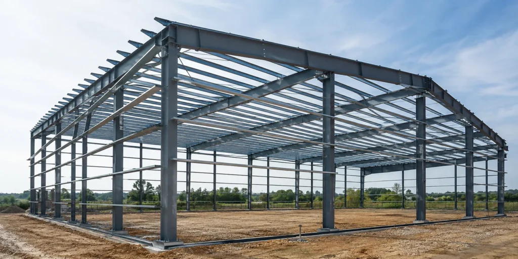
Main Frames: Columns, Rafters, and Beams
Columns carry vertical gravity loads and horizontal wind or seismic forces down to the foundation. In pre-engineered metal buildings, columns are usually tapered built-up I-sections, deeper at the knee (where column meets rafter) and shallower at the base. This taper puts steel where bending moments are highest, saving material.
Rafters span between columns across the roof. They’re also tapered in most pre-engineered designs, deepest at the knee and at midspan. In conventional steel construction, you’ll see hot-rolled wide-flange beams (W-shapes) or open-web steel joists instead.
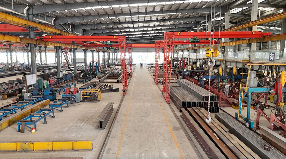
Crane beams deserve special mention for industrial facilities. These are heavy, stiff members mounted to the columns that support overhead bridge cranes. A 20-ton crane imposes significant vertical and lateral forces, so crane beams are often the heaviest individual members in the building.
Secondary Framing: Purlins, Girts, and Eave Struts
Purlins run horizontally across the roof, spanning between rafter frames. They support the roof panels and transfer wind uplift and snow loads into the primary frames. Cold-formed Z-shapes and C-shapes (typically 8 to 12 inches deep) are the most common purlin profiles. Z-purlins can be lapped at supports, creating a continuous beam effect that increases their load capacity by roughly 20% compared to simple-span C-purlins.
Girts do the same job on the walls, supporting wall panels and transferring wind pressure to the columns. Eave struts sit at the intersection of roof and wall, serving double duty as the last roof purlin and the top wall girt. They also help form the eave closure detail and contribute to the building’s lateral bracing system.
Steel Building Bracing Systems and Stability
A steel frame without bracing is like a bookshelf without a back panel: it can hold vertical weight but will rack sideways under any lateral push.
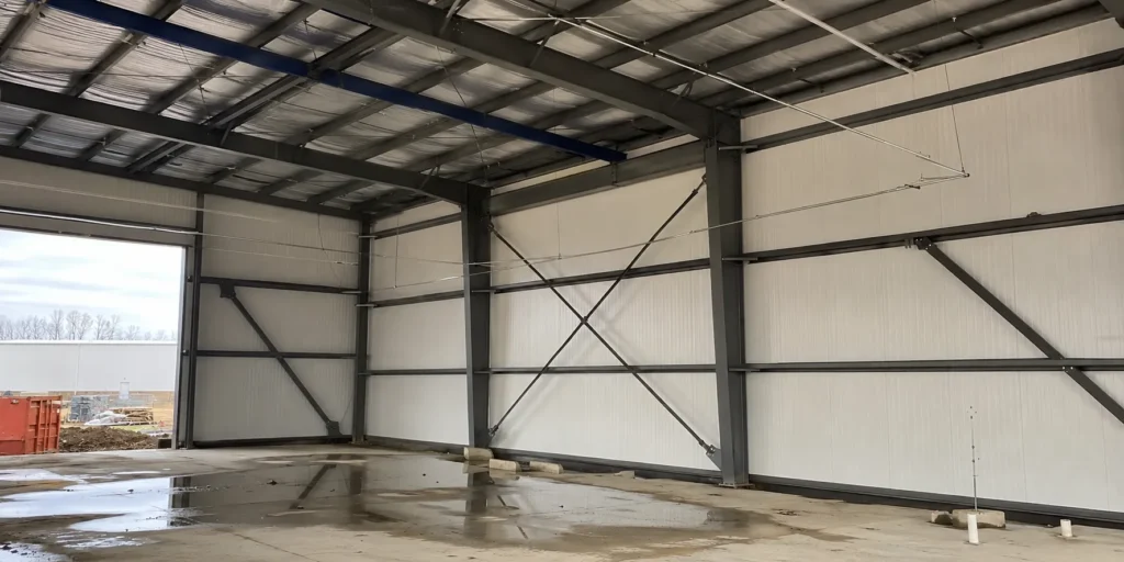
X-Bracing, Diagonals, and Portal Frames
X-bracing is the simplest and most cost-effective lateral bracing method. Steel rods or angles form an X pattern in selected wall bays and roof bays, creating triangulated load paths that resist wind and seismic forces. The rods work in tension only; whichever diagonal is in tension under a given load direction carries the force while the other rod goes slack.
Where X-bracing interferes with door openings or traffic flow, portal frames offer an alternative. A portal frame is essentially a rigid moment connection between a short column segment and a horizontal beam, creating a bracing bay that remains open for vehicle access. Portal frames cost more per bay than rod bracing, so engineers typically limit them to bays where openings are required.
Diagonal bracing using single angles or structural tubes is a middle ground, useful in situations where rod bracing lacks the stiffness needed for serviceability (drift limits, for instance).
Diaphragm Action and Wind Load Resistance
Roof and wall panels, when properly attached, act as diaphragms that transfer lateral loads to braced bays. This diaphragm action is real structural behavior, not a bonus. Engineers account for it in design, and the connection pattern (screw spacing, seam fastening) directly affects diaphragm strength.
Standing seam roof panels, because they float on clips, provide less diaphragm capacity than through-fastened panels. Buildings with standing seam roofs often need additional roof bracing (horizontal X-bracing in the roof plane) to compensate. Wind load resistance depends on the entire system working together: bracing, diaphragms, connections, and foundations all share the job.
Cladding and Roofing Options for Steel Warehouses
The cladding is the building’s skin. It keeps weather out, contributes to energy performance, and often represents 25-35% of the total building cost.
Single-Skin Metal Panels and Sandwich Insulated Panels
Single-skin panels are roll-formed steel sheets, typically 26 gauge (0.018 inches) for walls and 24 gauge for roofs. They’re inexpensive and fast to install but offer zero insulation value. For conditioned spaces, you’ll add fiberglass blanket insulation between the panel and the secondary framing.
Insulated metal panels (IMPs) sandwich a foam core – polyisocyanurate, mineral wool, or expanded polystyrene – between two metal skins. A 3-inch polyiso IMP delivers roughly R-23, which meets or exceeds most energy codes without additional insulation layers. IMPs also dramatically reduce air infiltration because each panel joint includes a tongue-and-groove interlock. The upfront cost is higher than single-skin plus blanket insulation, but labor savings and energy performance often close the gap.
Standing Seam vs. Screw-Down Roofing Systems
Screw-down (through-fastened) roof panels attach directly to purlins with self-drilling screws. They’re economical and provide strong diaphragm action, but the exposed fasteners are maintenance points. Over 15-20 years, screw gaskets degrade, and thermal cycling can elongate screw holes, leading to leaks.
Standing seam panels attach to purlins through concealed clips that allow the panel to expand and contract freely. No exposed fasteners means fewer leak points and longer service life. Standing seam systems dominate projects where longevity and low maintenance matter: cold storage facilities, food processing plants, and any building where the owner plans to hold the asset long-term.
Industrial Steel Building Foundation Requirements
The foundation anchors everything above it to the ground. Get it wrong, and you’ll see cracked floors, misaligned crane rails, and doors that won’t close.

Slab-on-Grade and Pier Foundation Designs
Most steel buildings sit on a concrete slab-on-grade with thickened edges at column locations. The thickened edge (or isolated spread footing) distributes column loads over enough soil area to keep bearing pressures below allowable limits. A typical 60-by-120-foot warehouse on decent soil might use 36-by-36-inch footings, 18 inches deep, at each column.
Pier foundations go deeper, reaching past weak surface soils to competent bearing strata. Drilled piers (caissons) are common in areas with expansive clay or high water tables. For heavy crane buildings, combined footings or mat foundations handle the large overturning moments that crane operations produce.
The slab itself matters too. Industrial floors supporting forklifts need a minimum 6-inch slab with fiber or welded wire reinforcement, and the flatness specification (FF/FL numbers) should match the equipment requirements.
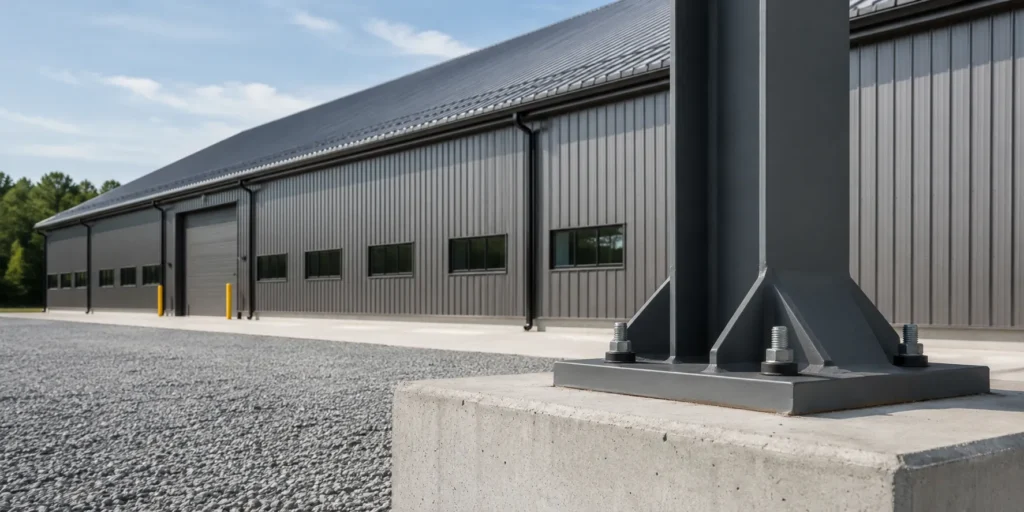
Anchor Bolt Placement and Tensioning
Anchor bolts connect the steel columns to the concrete foundation. Standard practice uses cast-in-place L-bolts or headed bolts set in a template before the concrete pour. Placement tolerance is tight: most erectors want bolts within 1/8 inch of plan location. A bolt group that’s off by half an inch can delay erection by days while the crew redrills base plates or installs field corrections.
For moment-resisting column bases (common in high-seismic zones or crane buildings), anchor bolts must resist both tension and shear. These bolts are larger diameter (often 1.5 to 2 inches), embedded deeper, and sometimes post-tensioned to ensure the base plate stays in full contact with the concrete under load reversals.
Accessory Components and Finishing Elements
Beyond the primary structure, a steel building needs gutters, downspouts, ridge caps, trim, doors, windows, ventilation systems, and sometimes mezzanines or canopies. These accessories don’t carry major structural loads, but they affect weather-tightness, appearance, and functionality. Translucent wall and roof panels bring in natural daylight, reducing energy costs. Ridge ventilators and exhaust fans manage heat buildup in unconditioned warehouses. Personnel doors, overhead doors, and loading dock equipment need proper framing and headers sized for the opening.
The components of a steel structure building work as a system. A decision about roofing type affects bracing design. Foundation sizing depends on frame geometry. Cladding selection influences energy performance and long-term maintenance budgets. The best outcomes happen when all these elements are coordinated early, during design, rather than patched together during construction. If you’re planning a steel building project, start by assembling a team – engineer, fabricator, and erector – that communicates well and understands how each component affects the others. That single decision will save you more money and headaches than any individual material upgrade ever could.
For additional guidance on structural steel design and weather-related load requirements, visit the American Institute of Steel Construction and the American Society of Civil Engineers.