Author:David Ran
This article discusses steel building components, fabrication, and project planning. Project-specific technical requirements should be confirmed during engineering review.
Share This :
Understanding Steel Building Load Calculations
Steel building load calculations establish every action a building must resist before engineers select rafters, columns, bracing, connections, anchor bolts and foundations. The objective is not simply to make the frame stronger. It is to define realistic design loads, trace how they move through the structure and check the combinations that can control strength, stability and serviceability.
A warehouse in a high-wind coastal area, a workshop with overhead cranes and an agricultural building in a heavy-snow region may have similar dimensions but very different structural demands. Accurate calculations therefore begin with the project location, building use, geometry, materials and operating equipment—not with a standard steel section schedule.
This guide explains the principal design loads, load paths, combinations and engineering checks used for industrial steel buildings. It is intended to help owners and project teams understand the process; final values must be determined by a qualified structural engineer using the locally adopted codes and verified project data.
What Are Design Loads?
A design load is a force, weight, pressure, imposed movement or acceleration that affects a building. Some loads act continuously, such as the self-weight of the steel frame. Others are temporary or environmental, including stored goods, wind, snow and earthquakes. Loads may act downward, upward, horizontally or in several directions at once.
In practical structural design, engineers must answer five questions:
- Which loads can occur at the project site?
- How large is each load and where does it act?
- How is it distributed over the roof, floors, walls or equipment supports?
- How does it travel through the framing system to the foundations?
- Which code-prescribed combinations produce the most demanding effects?
A load calculation is complete only when these actions are converted into member forces, reactions, deflections and connection demands that can be checked against defined acceptance criteria.
Information Required Before Calculating Loads
Reliable inputs are essential. Preliminary assumptions may be acceptable for budgeting, but they must be identified and confirmed before fabrication drawings are released. A typical design brief should include:
- Project address, elevation and surrounding terrain
- Building length, width, eave height, roof slope and bay spacing
- Intended occupancy and operational use
- Roof, wall, insulation and ceiling specifications
- Floor areas, mezzanines and storage arrangements
- Overhead cranes, conveyors, tanks, ducts and suspended services
- Solar panels or future roof-mounted equipment
- Door openings, canopies and partially open walls
- Geotechnical data and foundation constraints
- Local wind, snow, rain, seismic and temperature criteria
- Applicable building code, design standard and importance category
Large openings and future equipment are particularly important. A door can change internal wind pressure, while an unreported suspended service can add permanent load to purlins that were originally designed only for roof cladding.
1. Dead Loads
Dead loads are the permanent weights of the building and fixed components. They normally include primary frames, purlins, girts, bracing, roof and wall panels, insulation, ceilings, gutters, fixed platforms and permanently attached mechanical or electrical systems.
The basic relationship is straightforward: dead load = material unit weight × volume. For sheeting, insulation and ceiling systems, manufacturers often provide an area weight. The value is then assigned to the supporting members according to their tributary area.
Steel self-weight is usually refined during analysis. Engineers begin with an estimated frame weight, size the members and allow the analysis model to update the calculated weight. This iteration continues until the assumed and selected sections are consistent. Heavy fireproofing, photovoltaic systems, ducts and suspended process lines should be listed separately so they are not hidden inside an optimistic allowance.
2. Live Loads
Live loads result from occupancy, maintenance and movable items. They can change in magnitude and position during the building’s life. The required value depends on how an area will be used rather than on the framing material.
- Roof live load: temporary maintenance personnel, tools and movable materials on the roof.
- Floor live load: people, movable furniture, forklifts or general operational loading.
- Storage load: pallet racks, stacked materials or dense stored products.
- Mezzanine load: occupancy and storage loads applied to an elevated floor.
- Concentrated load: a local wheel, machine leg or other point action that may govern even when the average area load is modest.
A common error is to use a uniform floor load without checking concentrated loads or actual rack layouts. Another is to assume a future mezzanine can be added without affecting columns, bracing, base plates or foundations. Planned expansion should be defined during the initial steel building load calculations.
3. Wind Loads on Steel Buildings
Wind can push against walls, create suction on leeward surfaces and lift roof panels away from the structure. For lightweight steel buildings, wind uplift may control purlins, fasteners, bracing, anchor bolts and foundations even when gravity loads control the main rafter design.
Wind pressure is related to the square of wind speed, so a moderate increase in the design speed can create a much larger pressure. The complete procedure also considers risk category, terrain exposure, topography, building height, directionality, enclosure classification, gust effects and external pressure coefficients.
Main Wind Design Considerations
- External pressure: pressure or suction acting on walls and roof zones.
- Internal pressure: pressure inside the building, strongly influenced by openings.
- Components and cladding: local pressures on panels, fasteners, purlins and girts.
- Main wind-force-resisting system: the portal frames and braced bays that stabilize the complete building.
- Roof corner and edge zones: local regions where suction can be significantly higher than in interior zones.
Large roller doors and open-sided canopies require special attention. If a dominant opening is assumed incorrectly, internal pressure can be underestimated. Engineers should also confirm whether doors are designed to remain closed during severe weather or whether an accidental open condition must be checked.
4. Snow, Rain and Ice Loads
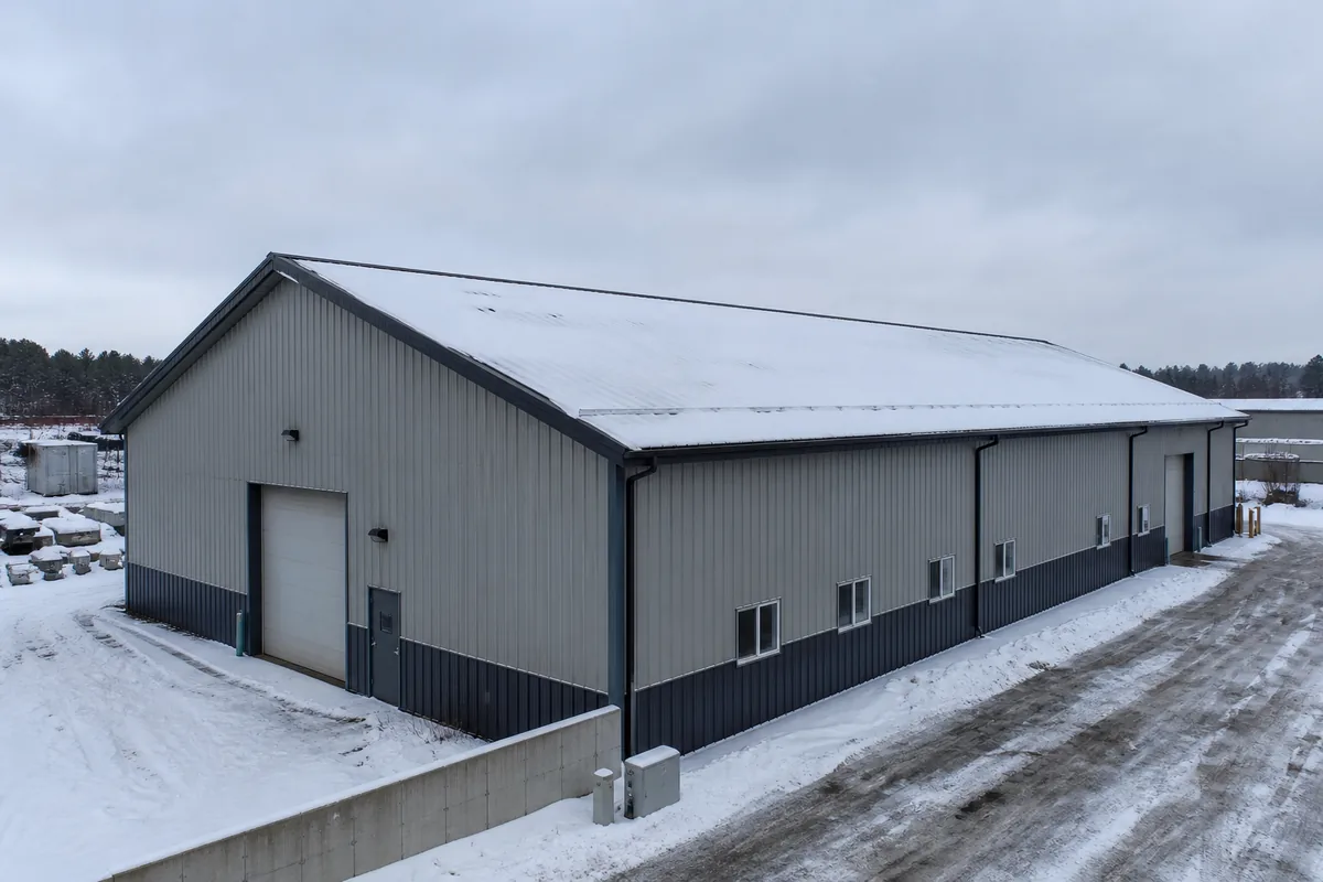
Ground snow data is converted into roof snow load by considering roof exposure, thermal conditions, importance and roof slope. The roof is then checked for balanced snow, unbalanced loading and local drift accumulation. Snow does not always settle evenly, and wind can move it toward parapets, height changes and adjacent taller structures.
Drift zones can control individual rafters and purlins even when the average roof load appears acceptable. Rain-on-snow conditions, sliding snow from an upper roof and ice accumulation may require additional checks. Roof drainage also matters: blocked outlets or insufficient slope can permit water to pond, increasing deflection and attracting still more water.
5. Seismic Loads
Earthquake action is generated by ground movement and the inertia of the building mass. The seismic design force therefore depends on the building weight, local ground-motion parameters, soil conditions, structural system, importance category, ductility and expected dynamic response.
Seismic design is more than applying a horizontal force to each frame. Engineers define the lateral-force-resisting system, distribute forces by level, check torsion and drift, and detail members and connections so the intended load path remains reliable. Bracing connections, collector elements, column bases and foundations must be compatible with the chosen system.
Light single-story steel buildings often have lower seismic mass than concrete buildings, but that does not remove the need for careful detailing. Heavy cladding, mezzanines, storage systems or equipment can substantially change the seismic demand.
6. Crane, Equipment and Operational Loads
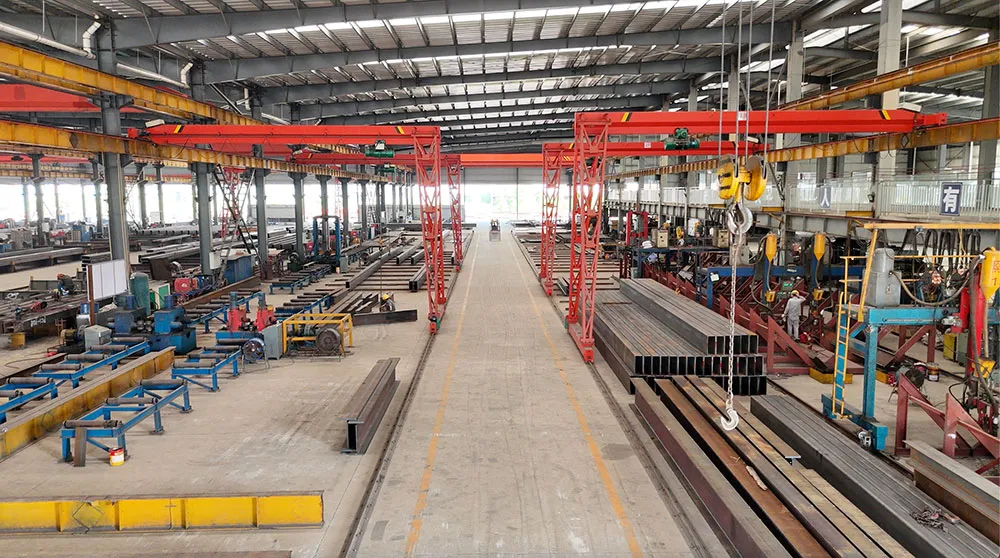
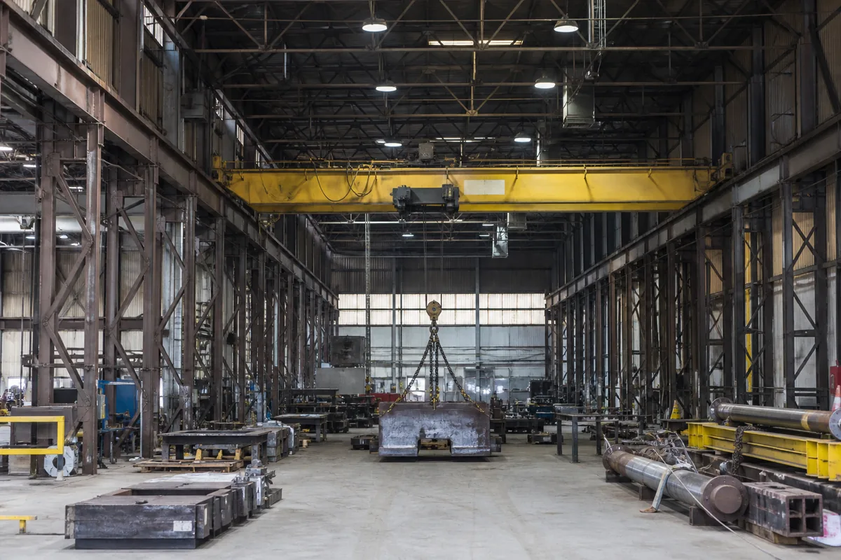
Industrial workshops frequently support actions that are not present in ordinary warehouses. Overhead cranes impose maximum and minimum wheel reactions, vertical impact, transverse surge and longitudinal braking forces. These loads affect crane runway beams, brackets, columns, bracing, foundations and movement joints.
- Rated crane capacity and crane self-weight
- Bridge span, wheel spacing and approach dimensions
- Maximum and minimum wheel loads
- Duty classification and operating frequency
- Vertical impact and lateral surge requirements
- Longitudinal forces from acceleration and braking
- Runway alignment, deflection and fatigue criteria
Other operational actions may come from conveyors, tanks, pipe racks, suspended production lines, rooftop units and vibrating machinery. Static weight alone may be insufficient; impact, vibration, start-up torque, thermal movement or maintenance access can govern the supporting steelwork.
7. Construction and Temporary Loads
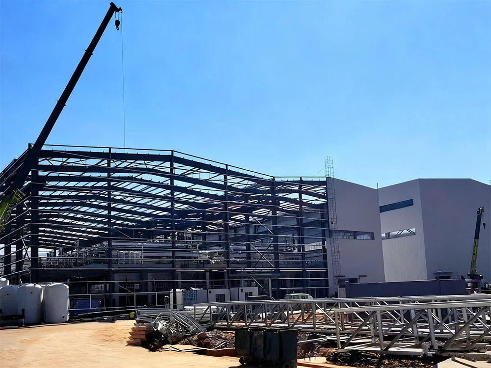
A completed frame gains stability from its full bracing system, diaphragms and connected bays. During erection, those elements may not yet be active. Temporary wind, stacked materials, lifting reactions and construction equipment can therefore create conditions that do not exist in the finished building.
The erection plan should identify the frame sequence, temporary bracing, crane positions, allowable material storage and the point at which permanent stability systems become effective. These checks protect both the structure and the installation team.
How Loads Travel Through a Steel Building
A clear load path connects every applied action to the ground. For a typical portal-frame building, gravity load follows this route:
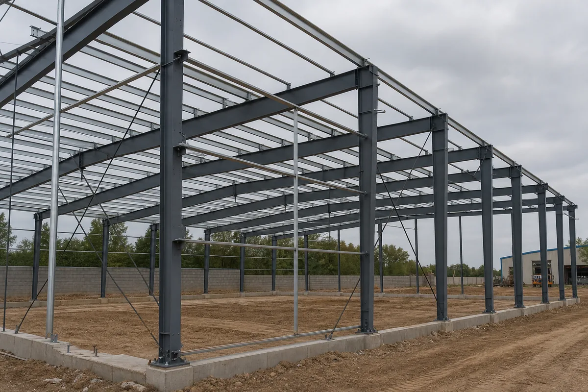
Roof panels → purlins → rafters → columns → base plates and anchors → concrete foundations → supporting soil
Longitudinal wind loads usually travel from the wall girts and roof purlins into vertical and roof bracing, then to the column bases and foundations. Transverse loads are commonly resisted by the portal-frame action of rafters and columns. Mezzanine loads pass through floor beams and columns, while crane loads follow runway beams and brackets into the main columns.
If any link is missing or weaker than assumed, the theoretical capacity of the other members cannot correct the problem. This is why connections, diaphragms, collectors, anchor rods and foundations are part of the same calculation process.
Steel Building Load Combinations
Buildings are not designed by adding every maximum load at the same time. Codes specify combinations that reflect the probability of different actions occurring together and the level of reliability required. Separate combinations may control gravity strength, wind uplift, seismic response, sliding, overturning or foundation bearing.
Two widely used approaches are Load and Resistance Factor Design (LRFD) and Allowable Strength Design (ASD). LRFD applies factors to loads and resistance, while ASD compares service-level combinations with allowable strength. Both methods can produce safe designs when applied consistently under the governing standard.
For U.S.-based projects, ASCE/SEI 7-22 provides nationally adopted criteria for dead, live, wind, snow, rain, seismic and other loads, together with load combinations. Structural steel members may then be designed using the ASD or LRFD provisions in ANSI/AISC 360. International projects must use the specific codes adopted by the local authority; values should never be copied from an unrelated country or previous project.
From Load Calculation to Structural Analysis
After design loads and combinations are defined, engineers construct an analytical model representing the geometry, member stiffness, restraints, releases and bracing system. Area loads are converted into line or point loads according to tributary widths. The model calculates reactions, axial forces, shear forces, bending moments, torsion and displacements.
Results are reviewed rather than accepted blindly. Engineers check whether reactions balance the applied loads, whether deflected shapes are reasonable and whether force reversals match the expected behavior. They also examine second-order effects, buckling lengths, diaphragm assumptions and connection flexibility where relevant.

Strength Checks
Primary and secondary members are checked for yielding, local buckling, lateral-torsional buckling, axial compression, bending, shear and combined actions. Connections are checked for bolt, weld, plate, block-shear and bearing limit states. Base plates, anchor rods and foundations are designed from the governing compression, uplift, shear and moment reactions.
Serviceability Checks
A building may be strong enough but still perform poorly if it deflects or vibrates excessively. Serviceability limits protect roof drainage, wall panels, doors, cranes, ceilings and occupant comfort. Typical checks include rafter deflection, purlin sag, column drift, crane runway alignment and vibration of floors or equipment platforms.
A Simple Conceptual Calculation Example
Consider a roof purlin spaced at 1.5 m supporting a combined unfactored downward roof load of 0.60 kN/m². Its tributary width is 1.5 m, so the basic line load transferred to the purlin is:
0.60 kN/m² × 1.5 m = 0.90 kN/m
The engineer then applies the governing code factors and checks bending, shear and deflection for the actual span and restraint condition. A separate wind combination may reverse the direction and create uplift. That uplift case can control the purlin-to-rafter fasteners even if the downward case controls purlin bending.
At the main frame, loads from multiple purlins are accumulated over the frame’s tributary bay. The analysis distributes them through the rafter and columns to the foundations. This simplified example illustrates the process, but it is not a substitute for project-specific engineering because real calculations must include all applicable loads, combinations, geometry and code provisions.
How Design Loads Affect Steel Building Cost
Higher design loads usually increase steel tonnage, connection capacity and foundation size, but the relationship is not uniform. Wind may increase bracing and anchors without greatly changing gravity beams. A crane can require stronger columns and foundations along only one production bay. Snow drift may govern a limited roof zone rather than the entire building.
- Higher basic wind speed or exposed terrain
- Heavy snow and drift accumulation
- High seismic demand or strict drift limits
- Wide clear spans and large bay spacing
- Heavy-duty overhead cranes
- Mezzanine floors and dense storage
- Large door openings or open-sided construction
- Heavy suspended services and rooftop equipment
- Weak soil or significant uplift reactions
Good engineering seeks an efficient load path and appropriate structural system instead of simply increasing every member. Early coordination can reduce unnecessary material while preserving safety and future flexibility. For related planning factors, see our guide to steel structure foundation design.
Common Load Calculation Mistakes
- Using wind, snow or seismic values from another location
- Ignoring internal wind pressure caused by large openings
- Applying only uniform snow and missing local drift zones
- Leaving solar panels, fire systems, ducts or ceilings out of dead load
- Checking average storage load but not concentrated rack or wheel loads
- Using crane capacity without complete wheel, impact and surge data
- Checking member strength while overlooking deflection, drift or vibration
- Assuming every model joint is rigid when the actual connection is not
- Sending incomplete reactions to the foundation designer
- Neglecting temporary stability during erection
These mistakes can result in redesign, fabrication changes or operational restrictions. A coordinated design basis and documented assumptions are much less expensive than correcting an incomplete load model after steel production begins.
What to Provide for Accurate Steel Building Load Calculations
When requesting a design and quotation, provide the project location, building dimensions, intended use, clear height, door sizes, roof and wall specifications, crane information, mezzanine layout, equipment loads, applicable design code and available geotechnical report. Identify future additions such as solar panels, production lines or warehouse racking.
If final data is unavailable, state which items are preliminary so appropriate allowances can be discussed. BF Steel Structure can coordinate the structural scheme, fabrication requirements and project-specific design inputs for warehouses, workshops and other industrial buildings. You can review our completed steel structure projects or contact our team with your layout and operating requirements.
FAQ About Steel Building Load Calculations
What loads must be considered for a steel building?
Typical projects consider dead, live, wind, snow, rain, seismic, temperature, equipment and construction loads. Industrial buildings may also require crane impact, surge, braking, vibration and concentrated storage loads. The governing list depends on the project location, use and adopted code.
Does a heavier steel frame always make the building safer?
No. Safety depends on a continuous load path, appropriate member stability, reliable connections, correct foundations and code-compliant detailing. Adding weight can also increase seismic demand. An efficient system is preferable to increasing members without understanding the controlling action.
Why can wind uplift control a steel building?
Steel buildings are comparatively light, so roof suction and internal pressure can exceed the downward permanent weight. This can reverse forces in purlins, connections, bracing and anchor bolts and may create foundation uplift.
Can load calculations be reused for a similar building?
A previous design can inform early planning, but it should not be reused without verification. Site hazards, geometry, openings, building use, equipment, soil and local code requirements can change the governing loads and combinations.
Do foundation loads come from the steel building analysis?
Yes. The structural analysis provides column reactions for relevant load cases and combinations, including compression, uplift, horizontal shear and moment. The foundation engineer combines these reactions with soil and concrete design requirements.
Conclusion
Accurate steel building load calculations connect site hazards and operating requirements to every part of the completed structure. Dead, live, wind, snow, seismic, crane and temporary loads must be defined, combined and transferred through a continuous path from cladding and equipment to the supporting soil.
The most economical result comes from complete project information, an appropriate framing system and careful coordination between structural, architectural, equipment and foundation design. Confirming the design basis early helps prevent overdesign, hidden deficiencies and costly changes after fabrication begins.
FAQ
① What is a steel structure building?
A steel structure building is a construction made primarily from high-strength steel components such as H-beams and columns. It is widely used for warehouses, workshops, poultry farms, and industrial facilities due to its durability and cost efficiency.
②How much does a steel building cost?
Steel building costs depend on dimensions, structural loads, material specifications, project location and the agreed scope of supply. A preliminary quotation can start with the main steel structure. Roof and wall panels, freight, foundations and installation should be considered separately when required. Customized solutions may vary based on specific requirements.
③How long does it take to build a steel structure?

Manufacturing lead times depend on the building dimensions, structural complexity, material specifications and production schedule. An estimated production timeline can be provided after reviewing the project requirements. Installation duration depends on site conditions, building complexity and the agreed scope of work.
④Do you provide installation support?
Installation documentation and technical support depend on the agreed scope of each project. If you require installation assistance, please let us know during the inquiry so we can review the available options, responsibilities and local requirements.
⑤Can steel buildings withstand extreme weather?
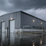
Steel buildings can be engineered for project-specific wind, snow and seismic loads, subject to applicable design codes, structural calculations and local site conditions. The required design loads and standards must be confirmed before structural engineering begins.