Industrial Steel Structures · Energy infrastructure
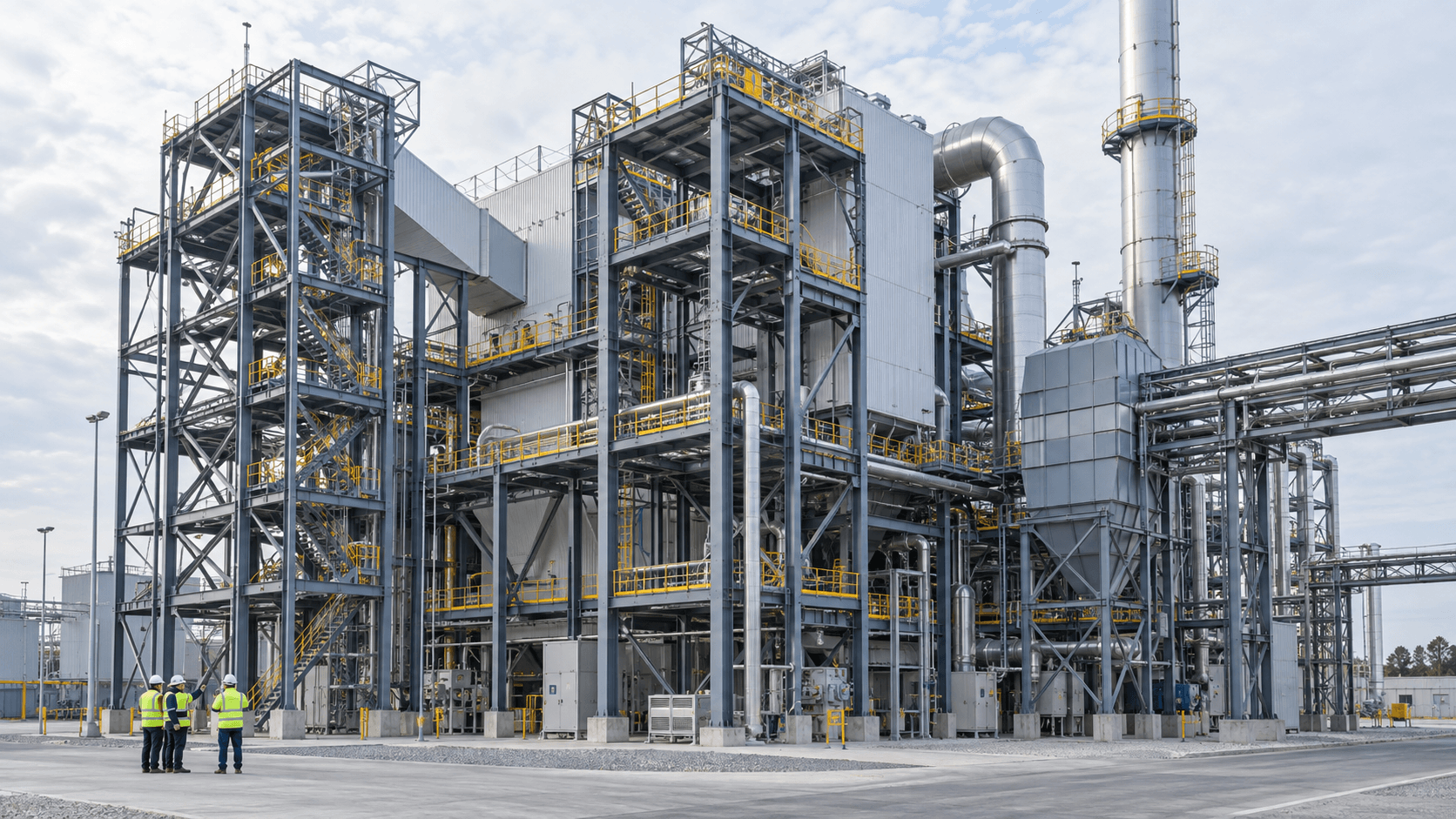
A waste-to-energy facility is not simply an industrial building with process equipment placed inside. Its structural frame must support heavy boilers, flue-gas equipment, ducts, conveyors, piping, cable routes, access platforms, cranes and enclosure systems while remaining stable through heat, vibration, maintenance activity and phased installation. A well-coordinated waste-to-energy plant steel structure therefore begins with process data, not a generic building grid.
For owners, EPC contractors and engineering consultants, the lowest steel price rarely identifies the lowest project cost. Missing equipment reactions, poorly planned thermal restraints or inaccessible connections can trigger redesign, site modification and commissioning delays. This guide explains nine design priorities, the information a fabricator needs, and the quality records buyers should compare before placing an order.
01 / Waste-to-energy planning
Waste-to-Energy Plant Steel Structure at a Glance
| Project Item | Typical Requirement | Buyer Verification |
|---|---|---|
| Primary frame | Multi-level braced or moment-resisting steelwork | Design basis, load combinations and analysis model |
| Equipment support | Boiler, turbine auxiliary, flue-gas and ash-handling interfaces | Certified reactions, dynamic data and anchor layout |
| Access | Platforms, stairs, ladders, monorails and removable zones | Operations and maintenance review |
| Environment | Heat, humidity, corrosive contaminants and outdoor exposure | Corrosivity category and coating schedule |
| Delivery | Shop-fabricated members or transportable modules | Shipping limits and erection sequence |
02 / Waste-to-energy planning
Where the Structural Steel System Fits
The structural scope may include a boiler support frame, tipping hall, waste bunker roof, turbine hall framing, flue-gas cleaning structure, ash-handling platforms, pipe racks, equipment skids and maintenance buildings. Boundaries vary by technology supplier and contract package. Before detailing starts, the responsibility matrix should state who designs equipment stools, embeds, anchor bolts, secondary platforms, cladding supports and temporary erection steel.
The governing code must be named in the purchase specification. International projects may reference Eurocodes, national standards or ANSI/AISC 360, which provides general requirements for structural steel buildings and other structures. Local building, seismic, fire, occupational safety and environmental rules still control where the plant is constructed. Bingfa can coordinate fabrication to the standard agreed in the contract; the engineer of record remains responsible for the project-specific design basis.
03 / Waste-to-energy planning
1. Define Equipment Loads Before Freezing the Grid
The first priority is a consolidated load register. It should identify operating, empty, test, upset and maintenance weights; equipment centers of gravity; nozzle and duct reactions; crane loads; platform live loads; wind and seismic actions; snow or rain loads; and accidental cases required by the local code. Loads should be tagged to drawing coordinates and revision numbers.
For a waste-to-energy plant steel structure, incomplete vendor data is common early in the schedule. The design team should distinguish confirmed reactions from allowances and set a date for final confirmation. Sensitivity checks can reserve reasonable capacity, but broad undocumented allowances make connections and foundations unnecessarily expensive. A controlled load register gives every party one auditable source.
04 / Waste-to-energy planning
2. Coordinate Process Equipment and Structural Interfaces
A waste-to-energy plant steel structure must coordinate boilers, economizers, air-pollution-control units, fans and ash systems that often come from different suppliers. Their support points may move as equipment design develops. A shared 3D coordination model helps locate columns, braces, maintenance openings and connection zones without blocking ducts, hoppers or access doors.
Interface control drawings should define support elevations, bolt patterns, allowable movements, tolerances and supply responsibility. Reviews must also consider installation clearance: equipment that fits in its final position may not have a viable lifting path. Early model reviews reduce field cutting and protect the integrity of the engineered frame. Our overview of steel building design requirements explains why accurate inputs are essential before fabrication release.
05 / Waste-to-energy planning
3. Evaluate Vibration and Other Dynamic Effects
Within a waste-to-energy plant steel structure, rotating fans, pumps, shredders, screens, conveyors and turbines can introduce periodic forces that are not represented by static weight alone. The engineer should obtain operating speeds, unbalanced forces, startup and shutdown conditions, and equipment-vendor acceptance limits. Natural frequencies, stiffness and damping assumptions may need specific evaluation to avoid resonance.
Dynamic performance also affects serviceability. Excessive platform movement can disturb instruments, loosen attachments and make operators uncomfortable even when member strength is adequate. Where required, separate inertia blocks, isolation systems or local stiffening should be coordinated with the global frame. Suppliers should never substitute heavier sections for a documented vibration assessment.
06 / Waste-to-energy planning
4. Allow for Thermal Movement
Hot ducts, boiler components and long pipe runs expand during operation. If the supporting steel restrains that movement unintentionally, secondary forces can enter beams, braces, anchors and equipment nozzles. The process designer should identify sliding, guided and fixed points together with temperatures and expected displacements.
A reliable waste-to-energy plant steel structure uses connection details that match those movement assumptions. Slotted holes, sliding bearings, flexible connections or expansion joints may be appropriate, but each must be designed for its actual load direction and inspected after erection. Fireproofing, grating and handrails should not bridge movement joints in a way that defeats them.
07 / Waste-to-energy planning
5. Design Access Around Operations and Maintenance
Access planning for a waste-to-energy plant steel structure treats platforms as production infrastructure, not leftover space between equipment. Safe access is required to valves, instruments, sampling ports, burners, soot blowers, motors and inspection doors. Clear widths, headroom, guardrails, toe plates, stair geometry, escape routes and fall-protection interfaces must follow the applicable local rules.
Maintenance strategy changes the steel layout. A fan rotor, motor or tube bundle may require a laydown area, removable handrails, lifting beams or a monorail. The design review should trace the complete removal route to a crane or external opening. These provisions add modest detailing effort early and can prevent expensive temporary works during every shutdown.
08 / Waste-to-energy planning
6. Specify Corrosion and Fire Protection by Exposure Zone
One coating system rarely suits an entire waste-to-energy plant steel structure. Outdoor frames, enclosed dry areas, humid waste-handling zones and surfaces near corrosive condensate have different exposure. The specification should define surface preparation, primer, intermediate and finish coats, dry-film thickness, color, repair method and inspection hold points. ISO 12944 provides a recognized framework for protecting steel structures with paint systems.
Fire protection is a separate performance decision. Depending on the fire strategy and local code, selected members may need intumescent coating, boards, spray-applied material or concrete encasement. Fireproofing thickness should be based on the required rating and section factor, not a universal value. Our guide to steel structure surface treatment covers blasting, painting and galvanizing selection in more detail.
09 / Waste-to-energy planning
7. Integrate Platforms, Ducts, Pipes and Cable Routes
Secondary steel can become a major share of the total tonnage. Grating supports, handrails, stairs, ladders, small-bore pipe supports, cable-tray brackets and cladding rails must be coordinated instead of added informally on site. Consistent attachment zones and standardized details simplify fabrication and future modifications.
Penetrations through beams or fire-rated assemblies require engineering approval. Site crews should not cut structural members to clear an unexpected service. A federated model, clash reviews and an agreed change process protect both schedule and structural capacity. The model should also carry member marks that connect design information to shop drawings and erection plans.
10 / Waste-to-energy planning
8. Control Fabrication, Welding and Traceability
Fabrication quality for a waste-to-energy plant steel structure begins with approved shop drawings and material identification. Buyers should request mill certificates, incoming inspection records, welding procedure specifications, welder qualifications, dimensional reports and non-destructive examination results at the level required by the inspection plan. The AWS D1.1 structural welding code is one commonly specified reference for welded structural steel; other project standards may apply internationally.
Critical connections deserve defined witness or hold points. Inspectors should verify joint preparation, fit-up, consumables, preheat when required, weld profile and acceptance criteria. Coating checks should record surface cleanliness, environmental conditions and dry-film thickness. See our structural steel fabrication process and quality-control guide for the document trail buyers can expect.
11 / Waste-to-energy planning
9. Plan Modular Delivery and a Stable Erection Sequence
Transportable modules can reduce elevated site work, but their size is limited by roads, ports, lifting capacity and site access. The fabricator should divide the frame into assemblies that can be manufactured, coated, shipped, lifted and connected without damage. Trial assembly may be valuable for congested or tolerance-sensitive interfaces.
The permanent analysis does not prove stability at every construction stage. Erection drawings should identify sequence, temporary bracing, crane loads, splice access, bolt-tightening requirements and survey checkpoints. Packing lists and member marks must follow the erection logic. A project-specific waste-to-energy plant steel structure package therefore combines design coordination with a practical logistics plan, not just a bill of steel.
12 / Waste-to-energy planning
Project-Engineered System vs. Generic Industrial Frame
| Comparison | Project-Engineered Waste-to-Energy Frame | Generic Industrial Frame |
|---|---|---|
| Load basis | Equipment reactions, dynamic cases and maintenance loads are coordinated | Predominantly uniform building loads |
| Thermal behavior | Fixed, guided and sliding interfaces are deliberately detailed | Thermal interaction may not be defined |
| Access | Platforms and removal routes follow operating tasks | General circulation only |
| Interfaces | Multidiscipline model and responsibility matrix | Limited process coordination |
| Quality records | Traceable inspection and turnover dossier | Basic delivery documents |
| Best use | Complex energy-from-waste and process facilities | Simple sheds and non-process buildings |
13 / Waste-to-energy planning
What to Include in Your RFQ
A comparable quotation depends on a comparable scope. Issue the design basis, general arrangement drawings, load register, equipment interface schedule, material grades, coating and fire-protection requirements, inspection and test plan, document submittal list, delivery destination and target schedule. State whether the supplier is pricing design, detailing, fabrication, coating, trial assembly, packing, shipping or erection support.
- Governing codes, design language and unit system
- Site wind, seismic, snow, temperature and corrosion data
- Confirmed and preliminary equipment reactions, clearly distinguished
- Model exchange format and drawing approval workflow
- Welding, bolting, NDT, coating and dimensional acceptance criteria
- Module dimensions, transport route and site lifting constraints
- Required turnover dossier, language and electronic file formats
14 / Waste-to-energy planning
What Controls Cost and Schedule?
Tonnage matters, but complexity often matters more. Numerous short members, heavy connections, thick plates, restricted weld access, special NDT, complex coating and repeated late revisions increase hours per tonne. Large modules may reduce site labor yet require temporary steel, trial fitting and special transport. Material availability and approval speed also affect the critical path.
The most reliable schedule separates model review, drawing approval, material procurement, fabrication, coating and shipping milestones. Early release packages can help only when their interfaces are stable. Freezing columns while equipment reactions remain uncertain may create more delay than it saves. For overseas delivery, allow time for robust packing, port handling and document review; our packing and shipping guide outlines key controls.
15 / Waste-to-energy planning
How to Select a Qualified Fabrication Partner
Evaluate evidence from comparable process structures, not only total annual capacity. Review engineering coordination capability, detailing software, material traceability, welding qualifications, NDT access, blasting and coating facilities, dimensional control and document management. Ask how design changes are recorded and how nonconformities are closed.
A capable partner should identify missing inputs, explain assumptions and provide a transparent deliverables register. The best proposal for a waste-to-energy plant steel structure makes technical responsibilities visible before the purchase order, reducing disputes during fabrication and erection.
Frequently Asked Questions
What is included in a waste-to-energy plant steel structure package?
Scope can include primary frames, equipment support beams, platforms, stairs, ladders, handrails, pipe and duct support steel, connection hardware, coating and erection drawings. The contract must define boundaries with equipment vendors, foundations, cladding and fire protection.
Which design standards can be used?
Bingfa can fabricate to internationally recognized or national standards specified for the project, including agreed AISC, Eurocode or other requirements. The engineer of record should confirm the governing edition, local code amendments, load criteria and acceptance rules before design release.
How long does fabrication take?
Lead time depends on engineering maturity, tonnage, connection complexity, material availability, inspection, coating and shipment lots. A moderate package may require several weeks after approved drawings and material release, while large multi-level structures are normally delivered in planned batches. A firm schedule follows scope review.
Can the steel structure be supplied as modules?
Yes, when transport routes, port limits, crane capacity and site access permit. Modules may include platforms, stairs and selected secondary steel. The lifting design, temporary bracing, trial assembly and shipping frames must be included in the module plan.
Which documents are supplied at handover?
A typical dossier may contain approved shop drawings, material certificates, welder and procedure qualifications, inspection and NDT reports, bolt records, coating reports, dimensional checks, packing lists and as-built revisions. The exact index should be agreed in the purchase order.
Discuss Your Waste-to-Energy Steel Package
A coordinated waste-to-energy plant steel structure supports safe operation, maintainability and predictable installation. Send Bingfa Steel Structure your general arrangement, equipment loads, applicable standards, delivery location and schedule. Our team can review the scope and prepare a project-specific fabrication proposal and quotation.
Contact us to review your project requirements →
Send a project enquiry ↑Phone / WhatsApp: +86 19006726230
Email: bingfasteelstructure@gmail.com