Author:David Ran
This article discusses steel building components, fabrication, and project planning. Project-specific technical requirements should be confirmed during engineering review.
Share This :
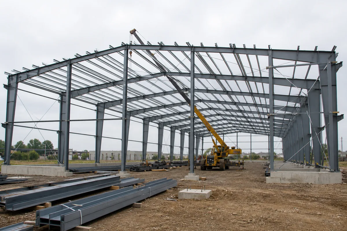
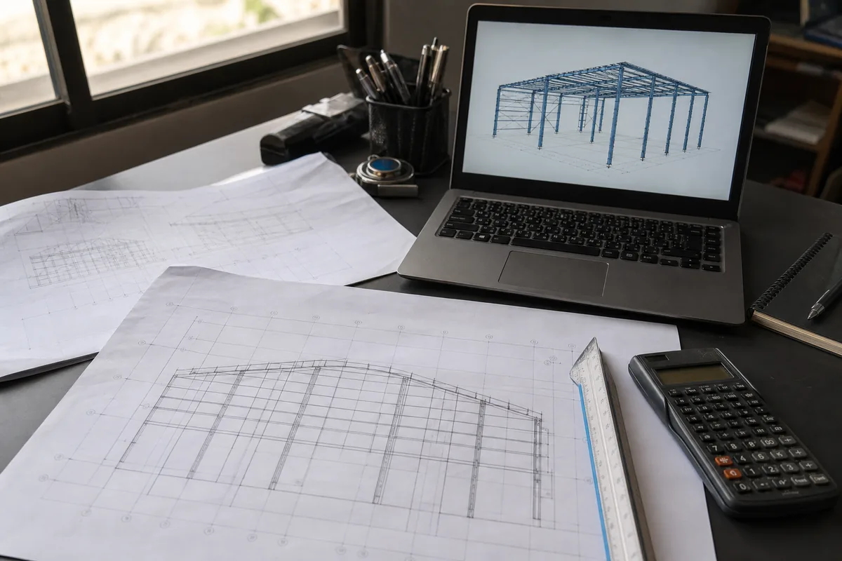
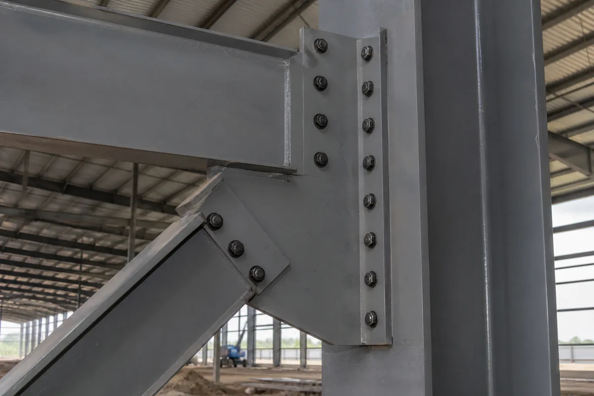
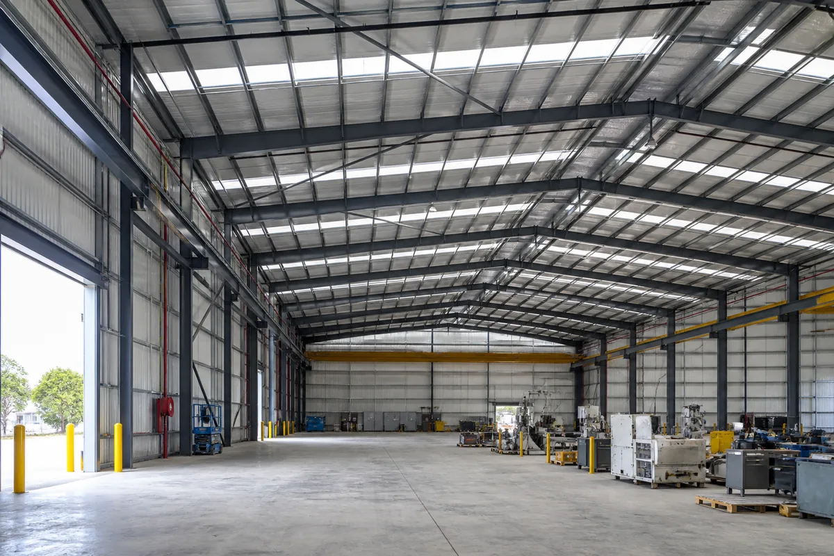
Steel structure building design is the coordinated engineering process that turns an owner’s operational requirements into a safe, buildable and economical structural system. It covers much more than choosing beam and column sizes. The design team must define the building geometry, evaluate site conditions and loads, select the framing and stability systems, design members and connections, coordinate foundations and services, and issue drawings that fabricators and erectors can use without ambiguity.
A successful steel building begins with clear information. Span, clear height, crane loads, mezzanines, storage systems, equipment, doors, local climate, seismic conditions and future expansion can all change the structural solution. When these requirements are established early, the engineer can optimize steel weight while protecting safety, serviceability and construction efficiency.
What Is Steel Structure Building Design?
Structural design determines how a building will carry gravity, wind, snow, seismic, crane and operational loads from the roof and floors down to the foundations. Engineers create a continuous load path through roof sheeting or deck, purlins, rafters, beams, columns, bracing, base plates, anchor bolts and concrete foundations. Every component must have adequate strength, stiffness, stability and durability for the intended use.
The work is iterative. An initial grid may look efficient architecturally but create heavy transfer members or interfere with production equipment. A very long clear span may improve operations yet increase rafter depth and foundation reactions. Good steel structure building design balances these competing demands rather than optimizing one component in isolation.
Step 1: Define the Building Requirements
The first step is to understand what the building must do. A warehouse, workshop, aircraft hangar, poultry house and multi-story commercial building may all use steel, but their grids, loads and performance criteria are very different. The owner and design team should agree on the functional brief before structural calculations begin.
- Overall length, width, eave height and required clear height
- Column-free zones, internal column locations and preferred bay spacing
- Roof slope, canopies, parapets, wall openings and dock arrangements
- Overhead cranes, monorails, conveyors, platforms and suspended services
- Mezzanines, offices, storage racks and future floor loads
- Fire-resistance, corrosion protection, insulation and environmental conditions
- Planned expansion, relocatable walls and possible future equipment
Changes made after the model and connections are developed can cause redesign, material waste and fabrication delays. A written design basis helps control revisions and gives the client, engineer, fabricator and contractor the same reference point.
Step 2: Collect Site and Design Data
Site information controls many design decisions. The engineer needs the project location, applicable codes, wind speed, terrain category, snow or rain data, seismic parameters, temperature range, exposure conditions and flood considerations. A geotechnical report should identify soil bearing capacity, settlement, groundwater, expansive soils, liquefaction risk and recommendations for shallow or deep foundations.
Topographic and utility surveys are also important. Finished floor level, drainage, retaining walls, underground services and adjacent structures affect column bases and foundations. If reliable soil data is unavailable, foundation assumptions must be stated clearly and verified before construction. Our guide to steel structure foundation design explains how column reactions and ground conditions are coordinated.
Step 3: Select the Structural System
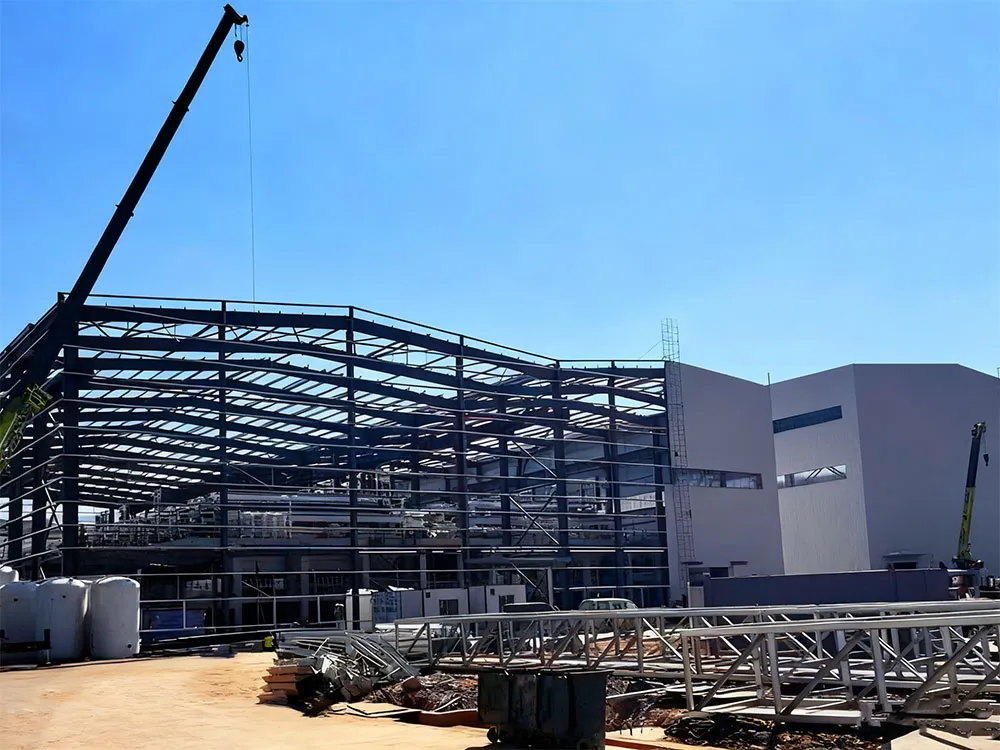
The structural system should match the building function, span, height, loading and local fabrication capabilities. Single-story industrial buildings often use rigid portal frames because they provide economical clear spans and fast erection. Roof trusses may be better for very wide spans, heavy suspended loads or long service zones. Multi-story buildings can use steel moment frames, braced frames or composite floor systems.
Primary Framing
Primary framing includes rafters, roof trusses, floor beams and columns. These members carry major gravity and lateral actions. Tapered welded sections can place steel where bending demand is highest, while hot-rolled sections may simplify procurement and connection detailing. The most economical choice depends on local material prices, fabrication equipment, transport limits and repetition.
Secondary Framing
Purlins, girts, eave struts and bridging support the roof and wall cladding while transferring wind and gravity loads to the primary frames. Their spacing must suit panel capacity, roof maintenance loads, insulation systems and service penetrations. Secondary members also help restrain the compression flanges of primary members.
Lateral Stability System
Rigid frames, vertical bracing, roof bracing and diaphragms stabilize the building against wind and earthquake effects. Braced bays must be positioned around doors, docks, windows and equipment. The stability concept should be fixed during concept design because moving a braced bay late can change member forces, foundations and erection sequencing.
Step 4: Determine the Design Loads
Accurate loads are the foundation of structural analysis. Engineers identify permanent loads from steel, cladding, floors and fixed services; imposed loads from occupants, storage and maintenance; and environmental loads from wind, snow, rain, temperature and earthquakes. Industrial projects may also include cranes, vibrating machinery, impact, fatigue, pipe racks, solar panels or suspended production lines.
- Dead load: self-weight of structural and permanently attached components
- Live load: occupancy, storage, maintenance and movable equipment
- Wind load: pressure, suction, internal pressure and uplift on the building envelope
- Snow and rain load: balanced, unbalanced, drifting and ponding conditions where applicable
- Seismic load: inertia forces based on site hazard, soil, mass and structural system
- Crane load: vertical wheel loads, impact, transverse surge and longitudinal braking
- Thermal effects: expansion, contraction and forces at restrained movement joints
Loads are combined according to the governing code so that unlikely actions are not simply added at full value. The engineer must also consider local effects such as wind around corners, snow drift beside parapets and concentrated reactions below equipment. For U.S.-based projects, the AISC Specification for Structural Steel Buildings provides generally applicable steel design requirements; every project must still follow its locally adopted codes and authority requirements.
Step 5: Build the Structural Analysis Model
The engineer creates a two-dimensional or three-dimensional analytical model representing member geometry, supports, releases, stiffness and load paths. The model calculates internal forces, reactions and deflections for the required load combinations. It must reflect actual behavior rather than simply reproduce the drawing geometry.
Boundary conditions require particular care. A nominally pinned base, partially restrained connection, diaphragm or flexible roof bracing can change the distribution of forces. Second-order effects account for additional moments caused by axial load acting through displaced geometry. Models should be checked using hand calculations, equilibrium reviews, deflected shapes and comparisons with expected structural behavior.
Step 6: Design Beams, Columns and Trusses
Once analysis forces are available, the engineer selects member sizes and verifies the relevant limit states. Beams and rafters are checked for bending, shear, lateral-torsional buckling, local buckling and deflection. Columns are checked for axial compression, combined axial load and bending, overall buckling and local slenderness. Truss chords, webs and gusset regions must resist axial forces while remaining stable between restraint points.
Strength alone is not enough. Excessive roof deflection can damage cladding or drainage, while floor vibration can affect occupants and sensitive equipment. Crane runway alignment and lateral movement may require tighter limits than a standard warehouse frame. Steel structure building design therefore includes serviceability criteria agreed with the client, equipment supplier and envelope designer.
Step 7: Design Bracing and Structural Stability
Bracing provides a reliable path for longitudinal wind, seismic and construction forces. Roof cross-bracing transfers actions to vertical braced bays, which then deliver them to the foundations. Flange braces and purlins restrain primary members against buckling. Each brace, rod, angle, cable, gusset and connection must be designed for the forces it actually carries.
Temporary stability is equally important. The completed envelope may provide restraint that is absent during erection. The erection method must specify temporary guys, bracing, frame sequencing and the point at which permanent bracing becomes effective. OSHA’s steel erection requirements in 29 CFR 1926 Subpart R are a useful U.S. reference, while local safety laws govern the actual project.
Step 8: Design Connections, Base Plates and Anchor Bolts
Connections turn individual members into a structural system. Common details include bolted end plates, flange plates, shear tabs, seated connections, gusset plates, splices and welded assemblies. Designers check bolts, welds, plates, block shear, bearing, prying action, local yielding and connection stiffness. Details should provide tool access, reasonable tolerances and a safe erection sequence.
Column bases transfer compression, uplift, shear and moment into concrete. Base plate dimensions and thickness depend on bearing pressure and bending, while anchor rods resist uplift and help position the column. Shear may be transferred through friction, anchor rods or a shear key. Grout thickness, edge distance, reinforcement congestion and template accuracy must be coordinated with the foundation drawings.
Step 9: Coordinate Foundations, Envelope and Building Services
The steel frame cannot be designed in isolation. Column reactions must be issued to the foundation engineer, including compression, uplift, shear and moment for governing combinations. Foundation flexibility may influence frame behavior, especially for moment-resisting bases or poor soil. Anchor bolt setting plans should be coordinated before concrete is placed.
Roof and wall panels require correct support spacing, movement allowances, fasteners and flashing. Large doors, louvers, windows and canopies create local framing and wind-pressure effects. Mechanical, electrical, fire-protection and process services need openings and supports that do not weaken primary members. Early coordination prevents unauthorized site cutting and difficult field modifications.
Design Drawings, Detailing and BIM Coordination
Design drawings communicate the structural intent: grids, levels, member sizes, design loads, bracing, connection forces, base reactions and required standards. Shop detailing then converts that information into individual part drawings, assemblies, bolt lists and erection marks. The engineer reviews submissions for consistency with the design intent, while the fabricator remains responsible for dimensions and manufacturing information defined by the contract.
A coordinated three-dimensional model can identify clashes between braces, ducts, cranes, conveyors and architectural elements before fabrication. BIM is most valuable when responsibilities, model accuracy and approval status are clear. It does not replace engineering judgment, calculations or disciplined drawing review.
Checking, Revisions and Design Release
Before drawings are released, another qualified engineer should review the design basis, load paths, computer model, governing combinations, member utilization, deflections, reactions and critical connections. The checker should be able to follow the assumptions without relying on undocumented conversations. Comments must be resolved and incorporated consistently in calculations, models and drawings.
Revision control is essential after procurement begins. Every issue should carry a clear status, date and revision description so that the workshop and site know which information is approved for construction. A late change to a door, crane or service opening may affect several drawings and fabricated parts. A formal change process allows the engineer to evaluate structural consequences before modified work proceeds.
Design Standards and Engineering Approval
The applicable standard depends on project location, authority and contract. Engineers may work with AISC, Eurocodes, British Standards, Chinese GB standards or other national systems. Loads, material grades, seismic detailing, fire protection, welding, bolting and quality control must form one compatible code basis. Mixing isolated provisions from different standards without a documented engineering basis can create gaps or inconsistent safety factors.
Final calculations and drawings should be prepared or reviewed by qualified professionals authorized for the project jurisdiction. Independent checking may be required for complex structures, long spans, unusual geometry, high seismic demand or public buildings. Approval should cover both structural calculations and the information needed for fabrication and erection.
Cost Optimization Without Reducing Safety
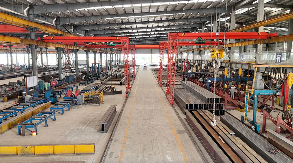
Efficient design reduces total project cost, not merely steel tonnage. Repeated bays, standardized plates, accessible bolts and fewer unique sections simplify detailing and fabrication. A slightly heavier member may save money if it eliminates a complicated stiffener or connection. Transport lengths, container dimensions, crane capacity and erection access can also control the economical solution.
- Align column grids with operations, racks and equipment
- Use repeated frame geometry and connection families
- Select locally available steel grades and section sizes
- Coordinate openings before analysis and fabrication
- Compare clear-span benefits against rafter depth and weight
- Plan expansion joints and future bays during initial design
- Evaluate fabrication, shipping and erection costs together
Optimization must not remove required load capacity, stability, robustness, fire performance or durability. The best result is a design that is easy to understand, manufacture, transport, erect, inspect and maintain.
Common Steel Building Design Mistakes
- Incomplete design brief: cranes, mezzanines or equipment are added after framing is finalized.
- Incorrect load assumptions: local wind, snow drift, seismic or internal pressure conditions are overlooked.
- Poor bracing locations: cross-bracing conflicts with doors, docks or production lines.
- Strength-only checks: deflection, vibration, ponding or cladding movement is not controlled.
- Uncoordinated bases: anchor rods, reinforcement and edge distances cannot be constructed as detailed.
- Overcomplicated connections: unnecessary plates, welds and unique details increase workshop time.
- No erection stability plan: the frame depends on components that are installed too late in the sequence.
- Late service openings: ducts and pipes require site cutting of structural members.
Information Needed Before Design Begins
Providing complete information allows the supplier to prepare a more accurate concept, quotation and schedule. At minimum, share the project location, building dimensions, intended use, preferred clear height, door sizes, roof and wall materials, crane or equipment data, mezzanine requirements, local design loads, geotechnical information and desired completion date.
Reference layouts, process diagrams and photographs of similar facilities can clarify the operational intent. If some data is unavailable, identify it as an assumption rather than leaving it undefined. You can also review our completed steel structure projects when discussing the required building type and layout.
FAQ About Steel Structure Building Design
How long does steel structure building design take?
The duration depends on building size, complexity and the completeness of project data. A straightforward single-story building can progress quickly, while cranes, mezzanines, complex equipment, special approvals or repeated client revisions require more time. Concept design, engineering calculations, approval drawings and shop detailing should be planned as separate stages.
What software is used to design steel buildings?
Engineers use structural analysis, member design, connection design, drafting and BIM software. The selected tools vary by company and code. Software accelerates calculations and coordination, but the engineer must define the model correctly, verify results and approve the final design.
Can a steel building be designed for future expansion?
Yes. End-wall columns, foundations, roof drainage, bracing and utility capacity can be arranged for future bays. The expansion direction and design assumptions should be documented at the beginning, because later removal of bracing or end-wall framing can affect stability.
Are foundations included in steel building design?
The steel engineer provides column reactions, base details and anchor requirements. Foundation design may be completed by the same team or a local civil or structural engineer, depending on the contract and jurisdiction. Both scopes must be coordinated using the same geometry, load combinations and soil information.
What is the most important design input?
No single input controls every project. Building use, site loads, soil conditions, span, height and equipment must be considered together. In practice, the most valuable input is a complete and stable design brief that clearly distinguishes confirmed requirements from assumptions.
Conclusion
Steel structure building design converts operational needs and site conditions into a complete load path, coordinated framing system and buildable set of details. The process begins with a clear brief, then progresses through data collection, system selection, loading, analysis, member checks, stability, connections, foundations and drawing coordination. Decisions made early have the greatest influence on safety, steel weight, fabrication efficiency and future flexibility.
For a reliable result, involve the structural engineer, architect, equipment suppliers, fabricator and erection team before the design is frozen. Clear responsibilities and accurate information reduce revisions and help the completed steel building perform as intended throughout its service life.
Get a Custom Steel Building Design Proposal
BF Steel Structure provides customized design, fabrication and project support for warehouses, workshops, agricultural buildings, hangars and commercial steel structures. Send us your project location, dimensions, intended use, loads and equipment requirements to receive a practical structural concept and quotation.
FAQ
① What is a steel structure building?
A steel structure building is a construction made primarily from high-strength steel components such as H-beams and columns. It is widely used for warehouses, workshops, poultry farms, and industrial facilities due to its durability and cost efficiency.
②How much does a steel building cost?
Steel building costs depend on dimensions, structural loads, material specifications, project location and the agreed scope of supply. A preliminary quotation can start with the main steel structure. Roof and wall panels, freight, foundations and installation should be considered separately when required. Customized solutions may vary based on specific requirements.
③How long does it take to build a steel structure?
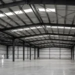
Manufacturing lead times depend on the building dimensions, structural complexity, material specifications and production schedule. An estimated production timeline can be provided after reviewing the project requirements. Installation duration depends on site conditions, building complexity and the agreed scope of work.
④Do you provide installation support?
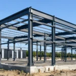
Installation documentation and technical support depend on the agreed scope of each project. If you require installation assistance, please let us know during the inquiry so we can review the available options, responsibilities and local requirements.
⑤Can steel buildings withstand extreme weather?
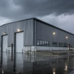
Steel buildings can be engineered for project-specific wind, snow and seismic loads, subject to applicable design codes, structural calculations and local site conditions. The required design loads and standards must be confirmed before structural engineering begins.