Author:David Ran
This article discusses steel building components, fabrication, and project planning. Project-specific technical requirements should be confirmed during engineering review.
Share This :
Seismic design of steel buildings addresses the inertia forces and deformations caused by earthquake ground motion. It requires a suitable lateral force-resisting system and coordinated design of members, connections and foundations.
Understanding Seismic Design of Steel Buildings
Seismic design of steel buildings is the process of creating a structure that can resist earthquake-induced forces, control lateral movement, protect occupants, and avoid sudden collapse. It is not achieved simply by increasing the size of beams and columns. Reliable performance depends on selecting an appropriate seismic force-resisting system, providing a continuous load path, controlling drift, and detailing members and connections so that they behave in a predictable and ductile manner.
Steel is well suited to earthquake-resistant construction because it combines high strength with low structural weight and can develop substantial ductility when properly detailed. However, those advantages only become effective when the entire building—from roof diaphragm and bracing to column bases, anchor bolts, and foundations—is designed as one coordinated system.
Why Earthquakes Require a Different Design Approach
Gravity loads act mainly downward and are comparatively stable. Earthquake ground motion accelerates the building horizontally and vertically, creating inertia forces that reverse direction repeatedly. The magnitude of these forces depends on seismic hazard, soil conditions, building mass, height, stiffness, dynamic characteristics, structural configuration, and the selected lateral system.
A building must possess both strength and deformation capacity. If it is strong but brittle, a connection or member can fracture without warning. If it is flexible but lacks adequate stiffness, excessive story drift may damage cladding, services, partitions, equipment, or adjacent buildings. Seismic engineering therefore balances strength, stiffness, stability, ductility, and constructability.
Information Required Before Seismic Design
- Project location and the legally adopted building code
- Mapped seismic hazard parameters or site-specific ground motions
- Geotechnical report, soil profile, site class, and liquefaction assessment
- Building use, risk category, importance, and required performance level
- Overall dimensions, roof height, bay spacing, mezzanines, cranes, and equipment
- Dead, live, snow, wind, storage, suspended, and operational loads
- Openings, irregularities, expansion joints, and architectural constraints
- Foundation type, allowable bearing conditions, and groundwater information
Incomplete site or operational information can produce an unsafe or uneconomical scheme. Early coordination between the owner, architect, geotechnical engineer, structural engineer, equipment supplier, and steel building manufacturer reduces late redesign.
Eight Key Principles of Seismic Design
1. Establish the Seismic Hazard and Site Conditions
The engineer first determines the earthquake ground-motion parameters required by the applicable code. Soil conditions can amplify shaking and influence the shape of the design response spectrum. Soft deposits, steep slopes, liquefiable soils, and nearby faults may require additional geotechnical study or site-specific analysis.
2. Minimize Seismic Mass
Earthquake inertia force is related to mass. Efficient steel framing, lightweight roof and wall systems, and careful control of permanent equipment loads can reduce seismic demand. Heavy machinery, tanks, rooftop units, storage platforms, and suspended utilities must still be represented accurately in the seismic weight.
3. Select an Appropriate Lateral System
The structural system must suit the building height, seismic hazard, architectural layout, required ductility, and fabrication capabilities. Common choices include moment-resisting frames, concentrically braced frames, eccentrically braced frames, buckling-restrained braced frames, and dual systems. Each has different stiffness, connection, detailing, and cost implications.
4. Provide a Complete Load Path
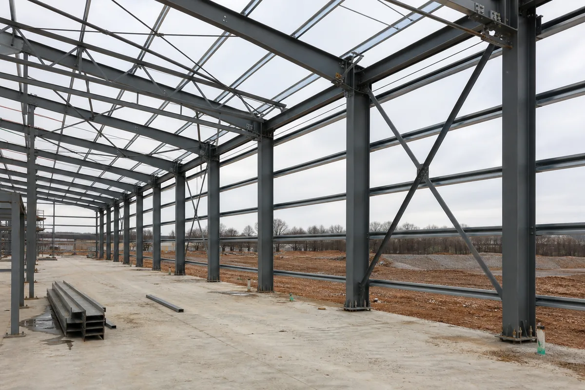
Seismic forces must travel continuously from the roof and floors through diaphragms, collectors, frames or braces, columns, bases, anchors, and foundations into the ground. A strong frame cannot protect a building if the diaphragm connection, collector, brace gusset, anchor rod, or footing interrupts that path.
5. Design for Ductility and Controlled Yielding
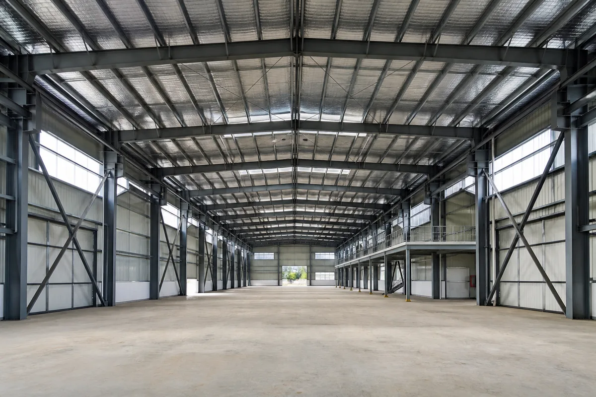
Ductility allows selected components to deform and dissipate earthquake energy without sudden loss of resistance. Capacity design intentionally identifies yielding regions and protects other components from brittle failure. Depending on the system, controlled yielding may occur in beams, braces, links, or specially designed connection components.
6. Avoid Weak Stories and Severe Irregularities
A soft or weak story concentrates deformation and can trigger instability. Sudden changes in building width, stiffness, mass, floor elevation, or bracing position can also create torsion and force concentrations. A regular, symmetrical arrangement normally produces clearer load paths and more predictable seismic behavior.
7. Control Drift and Second-Order Effects
Story drift is checked to limit damage and maintain stability. P-Delta effects occur when gravity loads act through laterally displaced columns, increasing moments and drift. Flexible frames, tall columns, mezzanines, and buildings with large open façades require careful stiffness and stability evaluation.
8. Detail Every Connection for the Intended Behavior
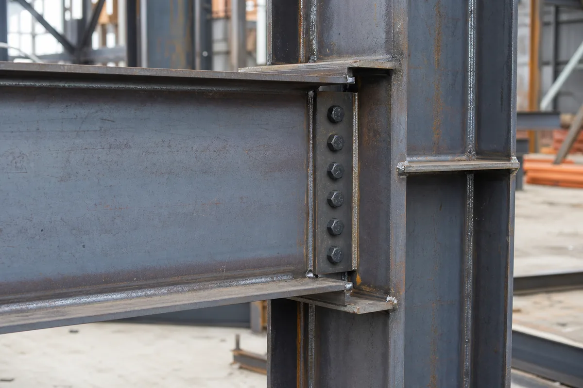
Seismic performance is often governed by connections. Bolts, welds, gusset plates, continuity plates, doubler plates, beam-column joints, brace intersections, splices, and column bases must accommodate the expected forces and deformations. Shop drawings and erection procedures should reflect the engineer’s assumptions.
How Seismic Loads Are Determined
Code-based seismic design generally begins with mapped ground-motion values, site coefficients, the design response spectrum, building risk category, seismic importance factor, structural period, seismic response coefficient, and response modification factor. These inputs establish the design base shear and its distribution over the height.
For regular low-rise buildings, an equivalent lateral force procedure may be permitted. Taller, irregular, or dynamically sensitive structures may require modal response spectrum analysis or another dynamic method. The analysis must include accidental torsion, diaphragm behavior, redundancy, orthogonal effects, and second-order effects where required.
ASCE/SEI 7-22 is a widely used reference for seismic actions and load combinations in U.S.-based and many international specifications. General steel member design is addressed by ANSI/AISC 360-22, while ANSI/AISC 341-22 adds seismic system, ductility, and detailing provisions. ANSI/AISC 358-22 covers prequalified connections for certain moment frames. The legally adopted local code always governs the project.
Steel Seismic Force-Resisting Systems
Moment-Resisting Frames
Moment frames resist lateral forces through bending in beams, columns, and rigid joints. They provide open interior and façade layouts, making them useful around large doors, retail fronts, equipment lines, and vehicle circulation. Their connections are demanding, and drift can govern member sizes. Ordinary, intermediate, and special moment frames provide different levels of ductility and are subject to different limitations.
Concentrically Braced Frames
Concentric braces create a stiff and efficient truss-like system. Common layouts include X, chevron, inverted-V, and single-diagonal bracing. Special concentrically braced frames require detailed attention to brace slenderness, compactness, gusset plate behavior, beam forces, and connections so cyclic brace yielding and buckling can occur without premature failure.
Eccentrically and Buckling-Restrained Braced Frames
Eccentrically braced frames use a short link that yields and dissipates energy while other components remain substantially elastic. Buckling-restrained braces are designed to yield in both tension and compression without conventional brace buckling. Both systems can combine high stiffness with reliable energy dissipation, but require specialized design, detailing, fabrication, and quality control.
Members, Connections and Capacity Design
Seismic design requirements may limit member width-to-thickness ratios, unbraced lengths, slenderness, material grades, and expected yield strength. Columns must resist combined axial load and bending while maintaining stability. Beams and braces require adequate lateral restraint, and protected zones must be kept free from attachments that could disrupt inelastic behavior.
Capacity design forces can be higher than the forces from a conventional elastic analysis. Connections, columns, collectors, and foundations may be designed for amplified or expected-strength forces associated with yielding of the designated energy-dissipating component. This hierarchy helps prevent bolt fracture, weld rupture, net-section failure, or unstable column mechanisms.
Diaphragms, Collectors and Bracing Layout
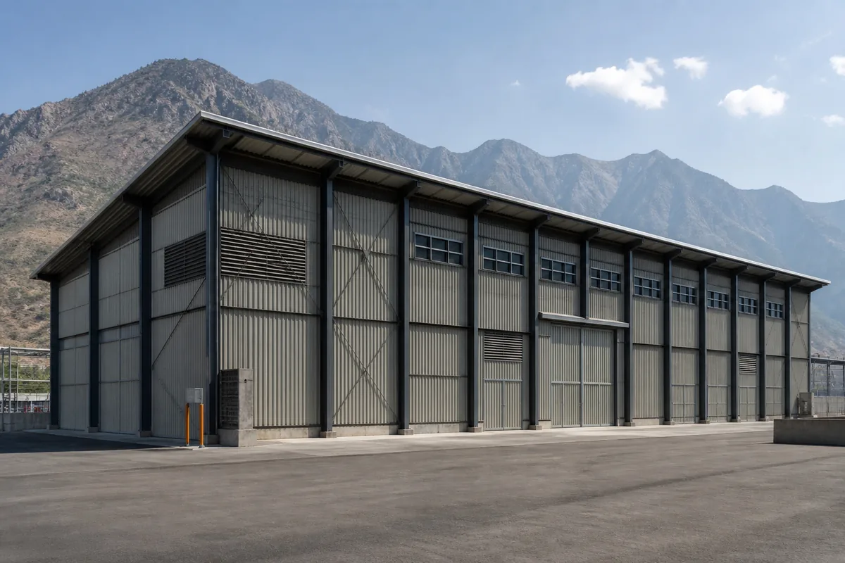
Roof deck, floor slabs, horizontal bracing, purlins, and their fasteners form or support the diaphragm. The diaphragm distributes lateral forces to the vertical resisting elements. Collectors and chords transfer forces around openings and between parts of the structure. Large skylights, roof monitors, mezzanine edges, conveyor penetrations, and interrupted bracing lines require explicit load-path checks.
Braced bays should be arranged to limit torsion and remain compatible with doors, production lines, cranes, and future expansion. If bracing is placed only on one side, the center of rigidity may be far from the center of mass, increasing rotational response.
Column Bases, Anchor Bolts and Foundations
Column bases transmit axial force, shear, and moment into the foundation. Base plates, anchor rods, welds, shear lugs, grout, reinforcing steel, concrete breakout zones, and footing stability must be coordinated. Depending on the analytical model, the base may be treated as pinned, partially restrained, or fixed; the actual detail should be capable of providing the assumed behavior.
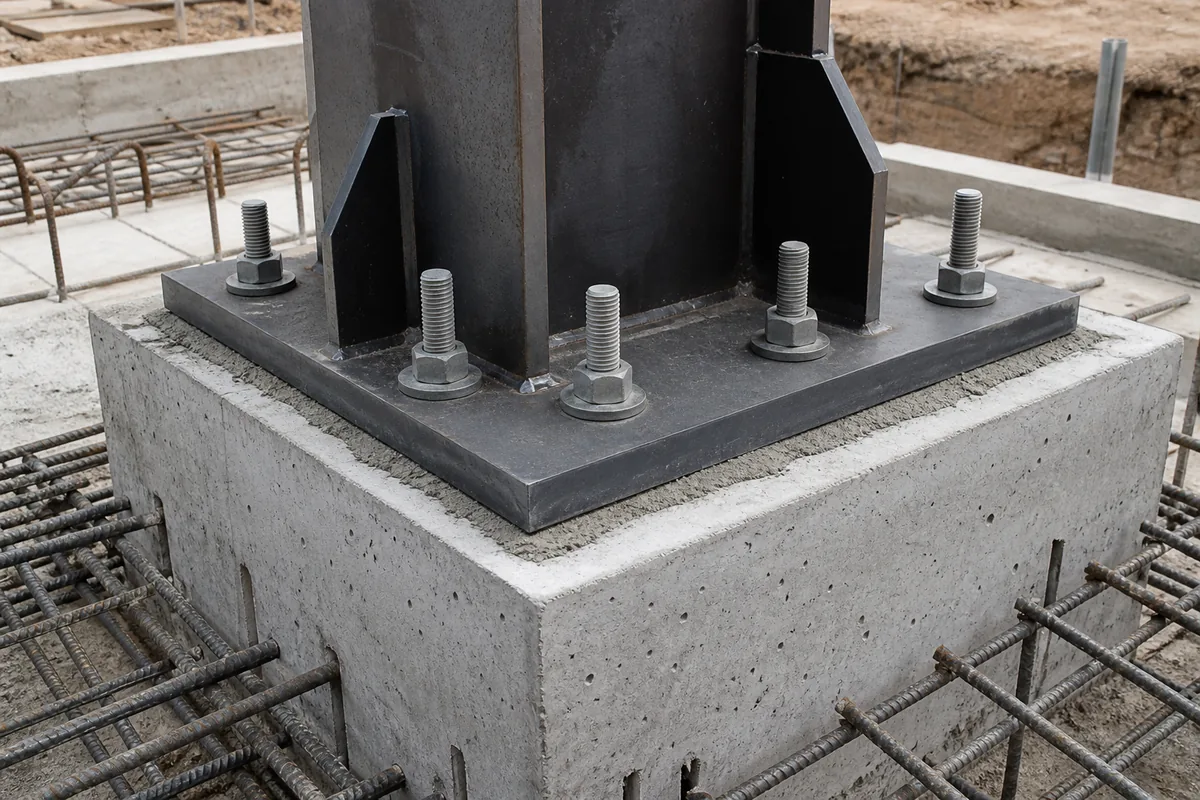
Foundation checks include bearing, sliding, overturning, uplift, soil-structure interaction, settlement, and connection to grade beams or slabs where required. More information about this interface is available in our guide to steel structure foundation design.
Seismic Load Combinations
Seismic effects are combined with dead, live, snow, and other applicable loads using the governing code’s strength or allowable-stress combinations. Both horizontal directions and load reversal must be considered. Vertical seismic effects, overstrength forces, redundancy, and simultaneous operational loads may also apply. Crane surge, suspended machinery, tanks, rack systems, and process piping need special coordination because they add mass and may impose independent dynamic demands.
Special Requirements for Industrial Steel Buildings
- Large door openings: relocate or redesign bracing without creating an interrupted load path.
- Overhead cranes: include crane dead load and coordinate runway forces with the seismic frame.
- Mezzanines: account for concentrated mass, diaphragm transfer, and discontinuous columns.
- Heavy equipment: provide anchorage and verify compatibility with building drift.
- Cladding: design wall panels, girts, fasteners, and joints for seismic movement.
- Future expansion: locate end-wall framing and joints so additions do not compromise the original system.
Common Seismic Design Mistakes
- Using a seismic hazard value without confirming the site class or local code
- Treating every steel frame as inherently earthquake resistant
- Selecting a response modification factor that does not match the detailing
- Ignoring diaphragm, collector, cladding, or equipment anchorage
- Creating a soft story with open ground-floor bays
- Concentrating bracing on one side and overlooking torsion
- Designing connections only for elastic analysis forces
- Assuming a fixed column base while detailing a flexible base
- Failing to coordinate shop fabrication and field welding requirements
- Changing openings or equipment after structural design without reassessment
How Seismic Requirements Affect Cost
Seismic design may increase steel tonnage, connection complexity, welding inspection, bracing, collectors, anchors, and foundation reinforcement. Cost is influenced by the site hazard, soil class, risk category, structural height, irregularity, chosen system, openings, equipment mass, and local fabrication capabilities. A regular building with aligned bracing and repetitive details is usually more economical than an irregular layout that requires transfer elements and customized connections.
Early structural input often saves more than late material optimization. Locating braced bays before architectural and equipment layouts are finalized can simplify the frame, foundations, and erection process while improving performance.
Information to Provide for a Seismic Steel Building Proposal
- Project country, city, and precise site location
- Applicable design code and required seismic parameters
- Building length, width, height, roof slope, and bay spacing
- Occupancy, risk category, and intended service life
- Geotechnical report and foundation recommendations
- Mezzanines, cranes, machines, tanks, racks, and suspended loads
- Door, window, skylight, and process opening locations
- Cladding, insulation, fire protection, and corrosion requirements
- Preferred fabrication, shipment, and erection scope
BF Steel Structure can coordinate structural layout, fabrication details, and project requirements for warehouses, workshops, agricultural buildings, and commercial facilities. Review our steel structure projects or contact our engineering team to discuss your project.
FAQ
1. Why is steel suitable for earthquake-resistant buildings?
Steel provides high strength at relatively low weight and can undergo substantial inelastic deformation when members and connections are properly proportioned and detailed. Its predictable fabrication also supports carefully controlled seismic systems.
2. Which structural system is best for a seismic steel building?
There is no universal best system. Moment frames provide open layouts, concentric braces offer efficient stiffness, and eccentric or buckling-restrained braces provide specialized energy dissipation. The best choice depends on hazard, height, drift limits, openings, function, cost, and local construction capability.
3. How are seismic loads calculated?
The engineer uses mapped or site-specific ground motions, soil coefficients, building mass, importance, structural period, system factors, and the applicable analysis procedure to determine base shear and distribute it through the building. The exact method is governed by the adopted code.
4. Do all steel buildings require special seismic detailing?
No. Required detailing depends on the seismic design category, risk category, selected system, and local code. Buildings in lower seismic regions may use systems with fewer special provisions, while high-seismic applications generally require more ductile systems and stricter detailing.
5. How does seismic design affect the price of a steel building?
Higher seismic demand can increase frame sizes, bracing, connection work, inspection, anchor systems, and foundation reinforcement. A regular layout, early bracing coordination, and repetitive details can control these costs without compromising safety.
Conclusion
Effective seismic design of steel buildings combines accurate hazard data, a suitable lateral system, controlled ductility, drift control, a continuous load path, and disciplined connection detailing. Every component must support the intended behavior—from roof diaphragm and braced bays to anchors and foundations. When architectural, operational, geotechnical, and fabrication requirements are coordinated early, a steel building can achieve reliable earthquake resistance with an efficient and constructible design.
FAQ
① What is a steel structure building?
A steel structure building is a construction made primarily from high-strength steel components such as H-beams and columns. It is widely used for warehouses, workshops, poultry farms, and industrial facilities due to its durability and cost efficiency.
②How much does a steel building cost?
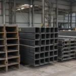
Steel building costs depend on dimensions, structural loads, material specifications, project location and the agreed scope of supply. A preliminary quotation can start with the main steel structure. Roof and wall panels, freight, foundations and installation should be considered separately when required. Customized solutions may vary based on specific requirements.
③How long does it take to build a steel structure?

Manufacturing lead times depend on the building dimensions, structural complexity, material specifications and production schedule. An estimated production timeline can be provided after reviewing the project requirements. Installation duration depends on site conditions, building complexity and the agreed scope of work.
④Do you provide installation support?
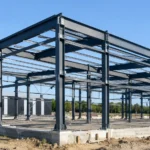
Installation documentation and technical support depend on the agreed scope of each project. If you require installation assistance, please let us know during the inquiry so we can review the available options, responsibilities and local requirements.
⑤Can steel buildings withstand extreme weather?
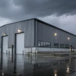
Steel buildings can be engineered for project-specific wind, snow and seismic loads, subject to applicable design codes, structural calculations and local site conditions. The required design loads and standards must be confirmed before structural engineering begins.